Transmitters, receivers, and transceivers including an optical bench

a technology for transceivers and receivers, applied in the field of optical benches, can solve problems such as difficulty in achieving sufficient alignment, practical implementation of optical communication systems, and difficulty in achieving accurate alignmen

Inactive Publication Date: 2005-03-22
LUMENTUM OPERATIONS LLC
View PDF24 Cites 37 Cited by
  • Summary
  • Abstract
  • Description
  • Claims
  • Application Information

AI Technical Summary

Problems solved by technology

One of the major obstacles to the practical implementation of optical communication systems is in the difficulty of achieving sufficiently accurate alignment in and of the various system and subsystem components of the optical communication system, and in maintaining that alignment for extended period of times. This is particularly true for the internal components of optical transmitters (e.g. a semiconductor laser, associated lenses, and other required components), which need to have accurate and sustained alignment for their entire operational life.
Moreover, another obstacle to the practical implementation of optical communication systems is that they must often operate in dirty and / or harsh environments—e.g. where particulates such as dust and liquids (e.g. water) are present.

Method used


Image

  • Transmitters, receivers, and transceivers including an optical bench
  • Transmitters, receivers, and transceivers including an optical bench
  • Transmitters, receivers, and transceivers including an optical bench

Examples


Embodiment Construction

In the following detailed description of the invention, numerous specific details are set forth in order to provide a thorough understanding of the invention. However, the invention may be practiced without these specific details. In other instances well known methods, procedures, components, and circuits have not been described in detail so as not to unnecessarily obscure aspects of the invention.

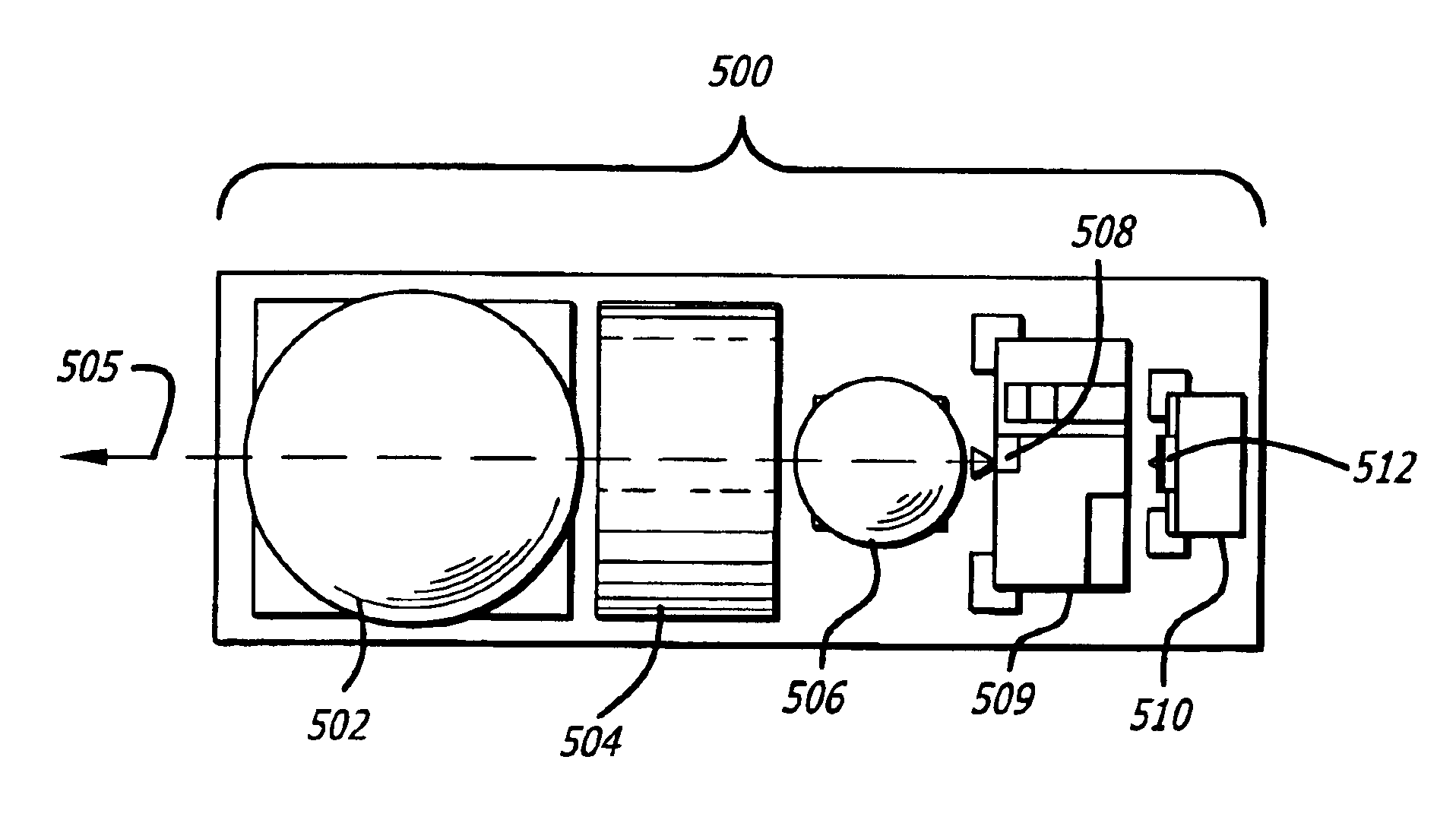
Generally, embodiments of the invention relate to optical transmitters, receivers, and transceivers including an optical bench. Optical transmitters may also be referred to as light transmitters, fiber optic transmitters, and fiber optic modules for transmitting an optical signal. Optical receivers may also be referred to as light receivers, fiber optic receivers, and fiber optic modules for receiving an optical signal. Optical transceivers may also be referred to as light transceivers, fiber optic transceivers, and fiber optic modules for transceiving optical signals. Collectively they ma...


PUM


Abstract

An optical transmitter includes an optical bench in one embodiment. A window frame is mounted to a mounting block having a groove to form the optical bench. Optic and electro-optic components of the optical transmitter are mounted to the optical bench. The window frame includes a plurality of openings for mounting one or more ball lenses, an optical isolator, and a semiconductor laser. The semiconductor laser chip is used to generate light signals for optical communication over an optical fiber. The one or more ball lenses may be mounted into ball lens openings of the window frame and extend into the groove of the mounting block. One of the ball lenses maybe used to focus light signals between an optical fiber and the optical transmitter. Another one of the ball lenses may be used to collimate the light output from the semiconductor laser. In another embodiment, an optical receiver includes the optical bench. In yet another embodiment, an optical transceiver includes the optical bench.

Description

FIELD OF THE INVENTIONThe invention relates generally to the field of optical data links and optical transmitters, receivers, and transceivers. Particularly, the invention relates to an optical bench and techniques for packaging optical transmitters, receivers, and transceivers.BACKGROUND OF THE INVENTIONOptical transmitters that utilize semiconductor lasers have become more important in recent years. One particularly significant application of these types of transmitters is in communication systems where fiber optic communication media is employed. With the growth in electronic communication, communication speed has become more important in order to increase data bandwidth in electronic communication systems. Improved transmitters can play a vital roll in increasing data bandwidth in communication systems using fiber optic communication media such as local area networks (LANs), metropolitan area networks (MANs) and wide area networks (WANs)(e.g. the Internet). A preferred component...

Claims


Application Information

Patent Timeline
Patent Type & Authority Patents(United States)
IPC IPC(8): G02B6/42
CPCG02B6/4208G02B6/4204G02B6/4292G02B6/4286G02B6/428G02B6/4244G02B6/4245G02B6/4265
Inventor CHIU, LIEW CHUANGCHUAN, RON PANG CHENGTAN, RONSON K.TAN, ERIC YOKE-THEE
Owner LUMENTUM OPERATIONS LLC
Why Eureka
Try Eureka