Electric compressor and control method therefor

a technology of electric compressor and control method, which is applied in the direction of machines/engines, liquid fuel engines, positive displacement liquid engines, etc., can solve the problem of imposing loads on the motor

Inactive Publication Date: 2005-03-22
TOYOTA IND CORP
View PDF18 Cites 70 Cited by
  • Summary
  • Abstract
  • Description
  • Claims
  • Application Information

AI Technical Summary

Benefits of technology

In another aspect of the method according to the present invention, an initial position of the rotor of the motor is estimated or detected when the electric compressor is activated. In a further aspect of the method according to the present invention, the motor is driven in a constant torque mode when the electric compressor is activated until the rotor rotates by the predetermined amount of rotation; and an operation mode of the motor is switched from the constant torque mode to a constant speed mode, when the rotor is driven by a predetermined amount of rotation from the initial position in the constant torque mode. In these methods, the similar effect may be obtained by the above mentioned function.

Problems solved by technology

When the compressor is driven in this state, an enormous load is applied on the motor.

Method used


Image

  • Electric compressor and control method therefor
  • Electric compressor and control method therefor
  • Electric compressor and control method therefor

Examples


Embodiment Construction

The embodiments of the present invention are described below by referring to the attached drawings.

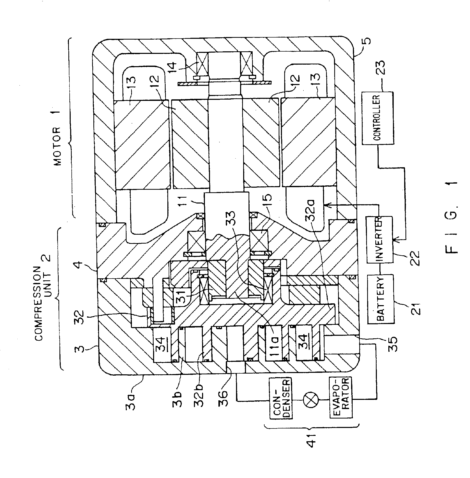
FIG. 1 is a sectional view of an electrically scroll-type compressor according to an embodiment of the present invention. This electric compressor comprises a motor 1 and a compression unit 2. The housing of the electric compressor comprises a fixed scroll 3, a center housing 4, and a motor housing 5. The fixed scroll 3 includes a fixed end plate 3a and a fixed spiral wall 3b extended from the fixed end plate 3a.

The motor 1 comprises a shaft 11, a rotor 12, a stator 13, etc. The shaft 11 is supported by the center housing 4 and the motor housing 5 with bearings 14 and 15. An eccentric shaft 11a is formed at the end of the shaft 11. The rotor 12 is fixed to the shaft 11, and rotates in synchronization with the shaft 11. The stator 13 is provided as encompassing the rotor 12. The stator 13 is provided with a plurality of salient poles, around each of which a coil is wound. The coil woun...


PUM


Abstract

When an electric compressor is activated, initial current data is selected by a selector, and a motor is driven with the torque corresponding to the initial current data. When the motor is driven by a ½ turn, the selector selects current difference data. The current difference data corresponds to an instructed speed. After the switch of the selector, the motor is driven to rotate at the instructed speed.

Description

BACKGROUND OF THE INVENTION1. Field of the InventionThe present invention relates to a method of controlling an electric compressor, and more specifically to a method of controlling a motor provided for an electric compressor.2. Description of the Related ArtAn electric compressor is widely used in various fields, for example, an air-conditioner, a refrigerator, etc.An electric compressor is provided with a motor, and realizes a cooling capability by compressing a refrigerant using the rotary motion of the motor. The motor is controlled such that, for example, it can be operated at a constant speed, based on difference between a user-specified temperature and the current actual temperature, etc.The speed of a motor (rotational speed) can be controlled basically by monitoring the position of a rotor using a position sensor such as a Hall device, etc. However, in the electric compressor, it is desired to use a system of controlling the speed of a motor by estimating the position of a ...

Claims


Application Information

Patent Timeline
Patent Type & Authority Patents(United States)
IPC IPC(8): F04B49/06F04B27/08F04B49/02F04C18/02F04C28/00F04C28/08F04C29/00H02P6/06H02P6/08H02P6/182
CPCF04B27/0895F04B49/065F04C18/0215F04C28/08F04C29/0085F04B2203/0207F04C2270/03F04B2203/0209F04B49/06F04C28/00
Inventor ODACHI, YASUHARUKIMURA, KAZUYAIEOKA, SHOICHI
Owner TOYOTA IND CORP
Why Eureka
Try Eureka