Device for the articulated connection of two bodies

Inactive Publication Date: 2005-03-22
SYNTHES USA
View PDF33 Cites 166 Cited by
  • Summary
  • Abstract
  • Description
  • Claims
  • Application Information

AI Technical Summary

Benefits of technology

The present invention relates to a joint-like connection of two bodies comprising a first body with a cavity extending coaxially to a central axis and containing a joint pan, a clamping member with a longitudinal axis and a coaxial bore, the clamping member having a shape complementary to that of the cavity and being resiliently deformable in a direction vertical to the longitudinal axis, at least one tension member insertable coaxially to the longitudinal axis into the bore and widening axially, so that an axial displacement of the at least one tension member within the bore may cause the clamping member to be expanded and releasably locked within the cavity, a second body which is releasably connectable to the first body by means of the at least one tension member and the clamping member, and a driving member by means of which the at least one tension member is axially displaceable relative to the bore. The driving member is connected with both the clamping member and the at least one tension member in such a way as to be axially in positive engagement while rotatable about the longitudinal axis.
The advantages of the first and second embodiments reside in their simplicity of manipulation whereas the third embodiment, due to the two threaded connections, permits a rapid releasing and tightening and, in addition, is easy to manufacture.

Problems solved by technology

A disadvantage common to all these connections realized by means of clamping cones consists in the difficulties encountered in releasing said connections, which often necessitates heavy hammer blows to be struck on the bone screw or the connecting member or which requires the aid of special instruments.

Method used


Image

  • Device for the articulated connection of two bodies
  • Device for the articulated connection of two bodies
  • Device for the articulated connection of two bodies

Examples


Embodiment Construction

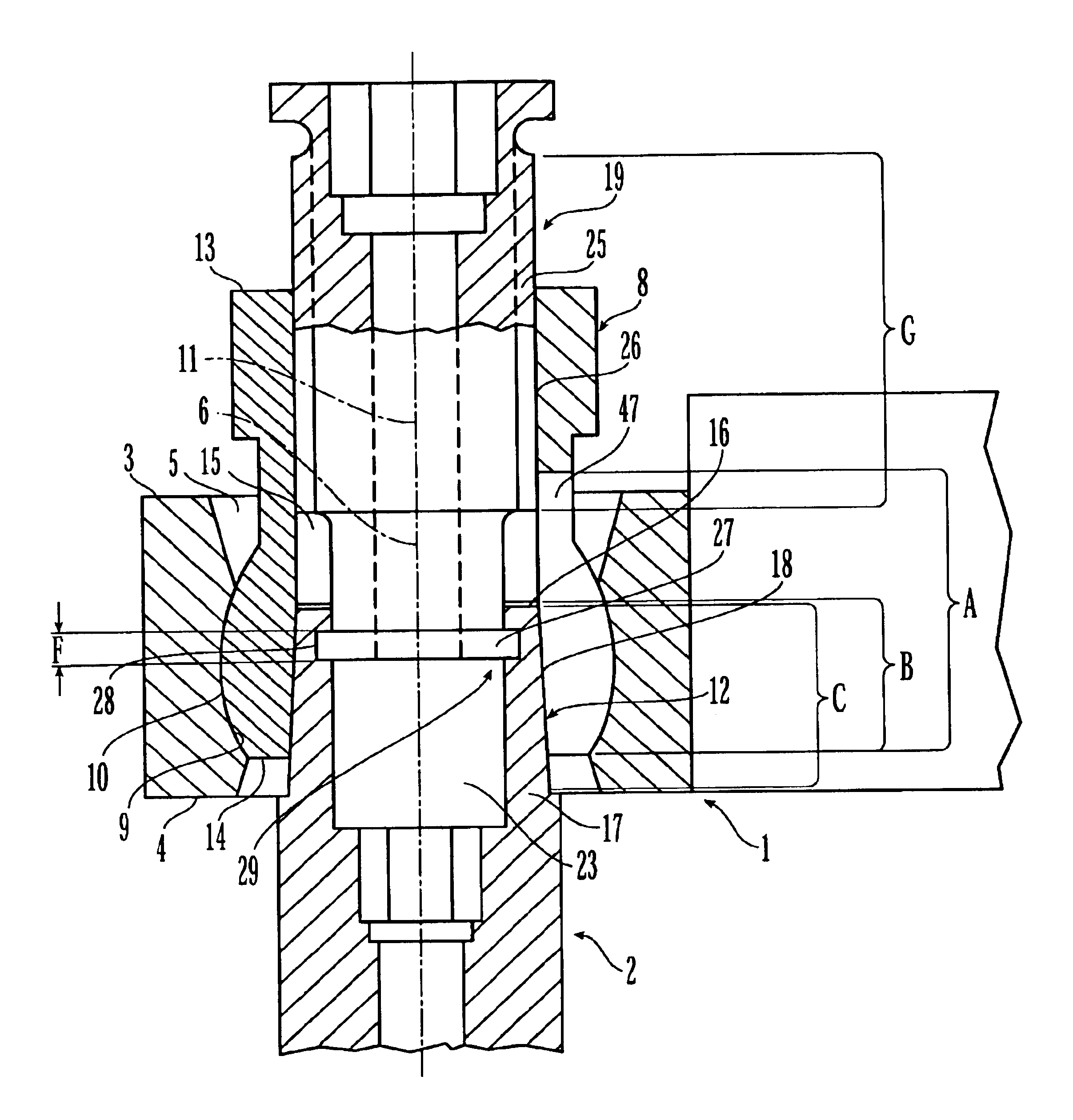
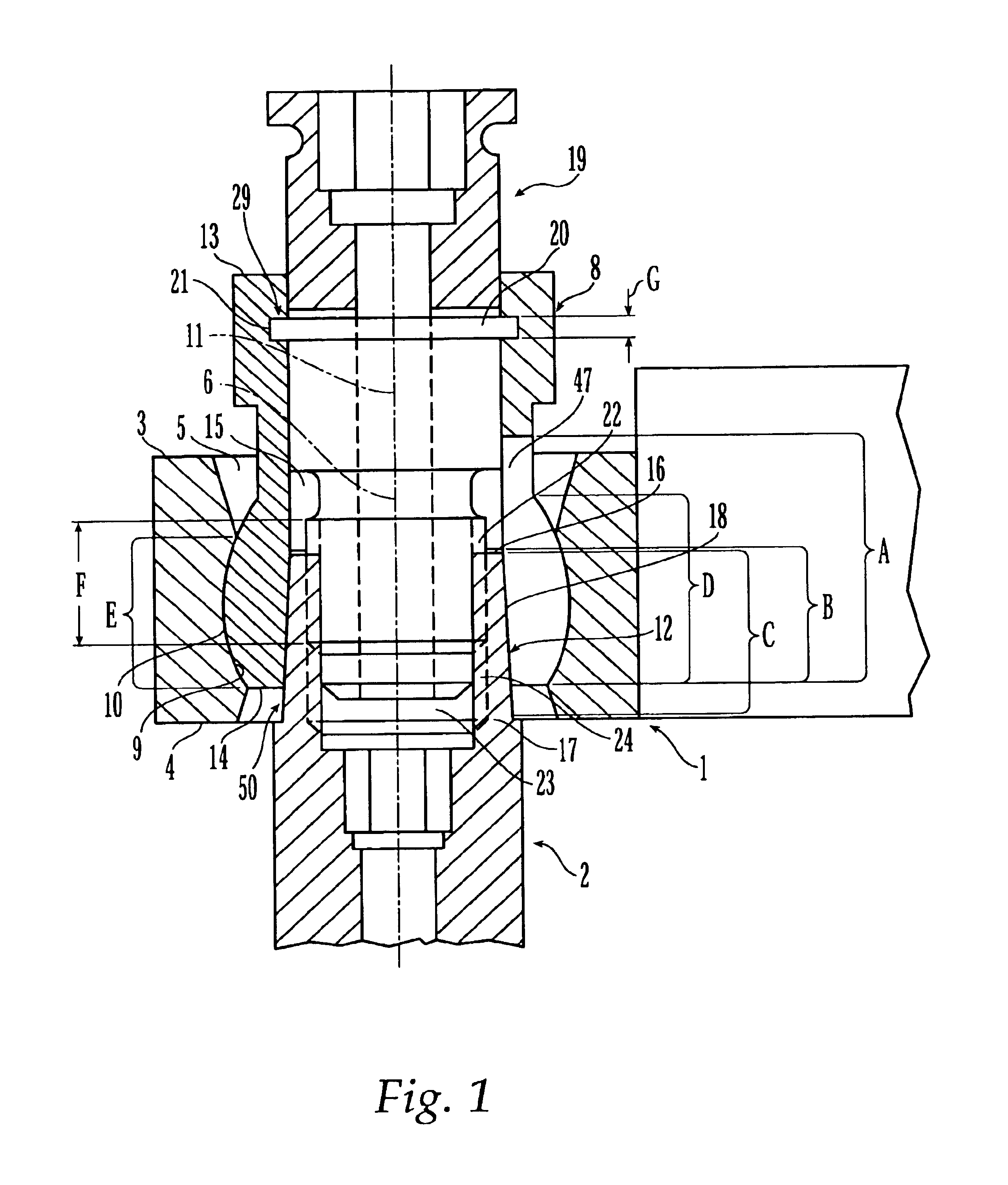
FIG. 1 shows one embodiment of the device according to the invention which comprises a first body 1 shaped in the form of a connecting member and a second body 2 shaped in the form of a pedicle screw. First body 1 includes a top surface 3, a bottom surface 4 extending parallel to the top surface 3, and a cavity 5 with a central axis 6 extending vertically to the top surface 3. Second body 2 is integral with a a tension member 12 and includes a clamping member 8, and a driving member 19 shaped in the form of a straining screw. The cavity 5 extends through the first body 1 coaxially to central axis 6 and comprises an axial longitudinal section E (N=1) which is spherically concave and rotationally symmetrical relative to the central axis 6. Corresponding to the spherically concave form of the longitudinal section E, clamping member 8 comprises a longitudinal section D (N=1), so that the clamping member 8 is rotatable within cavity 5 about the central axis 6 and about two other axes ext...


PUM


Abstract

A device is provided for the articulated connection of two bodies comprising a first body, a clamping member, at least one tension member, and a second body. The first body comprises a cavity extending coaxially along a central axis. The clamping included a longitudinal axis and a coaxial bore with at least one aperture, the clamping member being complementary to the cavity and resiliently deformable in a direction orthogonal to the longitudinal axis. The at least one tension member is insertable coaxially with respect to the longitudinal axis into the bore. An axial displacement of the at least one tension member within the corresponding aperture may cause the clamping member to be expanded to contact the cavity wall and be releasably locked within the cavity. The second body is releasably connectable to the first body by means of the at least one tension member and the clamping member. A driving member is provided for displacing the at least one tension member axially relative to the corresponding aperture, wherein the driving member is connected to both the clamping member and the at least one tension member in positive axial engagement while rotatable about the longitudinal axis.

Description

FIELD OF THE INVENTIONThe invention relates to a device for the articulated connection of two bodies and in particular to a fixation device for fixating two bodies in a joint-like connection.BACKGROUND OF THE INVENTIONIn the case of various surgical implants such as articulatedly connected, multipart bone plates and osteosynthetic vertebral column fixation devices where, for example, a longitudinal carrier extending approximately parallel to the vertebral column has to be attached by means of a number of bone screws, the joint-like connections must be releasably lockable. For this purpose, resilient tension members, such as collet chucks, are used. The locking of such joint-like connections is realized by means of an expansion of these resilient tension members within a corresponding cavity with fixed dimensions. This expansion process of resilient tension members is preferably achieved by means of clamping cones or clamping wedges.An osteosynthetic fixation device including a bone ...

Claims


Application Information

Patent Timeline
Patent Type & Authority Patents(United States)
IPC IPC(8): A61B17/60A61B17/80A61B17/68A61B17/64A61B17/70A61B17/58
CPCA61B17/60A61B17/7035A61B17/8047A61B17/7058A61B17/8038A61B17/7041A61B17/6466
Inventor SCHLAPFER, FRIDOLIN J.HESS, MARTIN
Owner SYNTHES USA
Why Eureka
Try Eureka