

Gas discharge tube
- Summary
- Abstract
- Description
- Claims
- Application Information
AI Technical Summary
Benefits of technology
Problems solved by technology
Method used
Image

Examples
first embodiment
(First Embodiment)
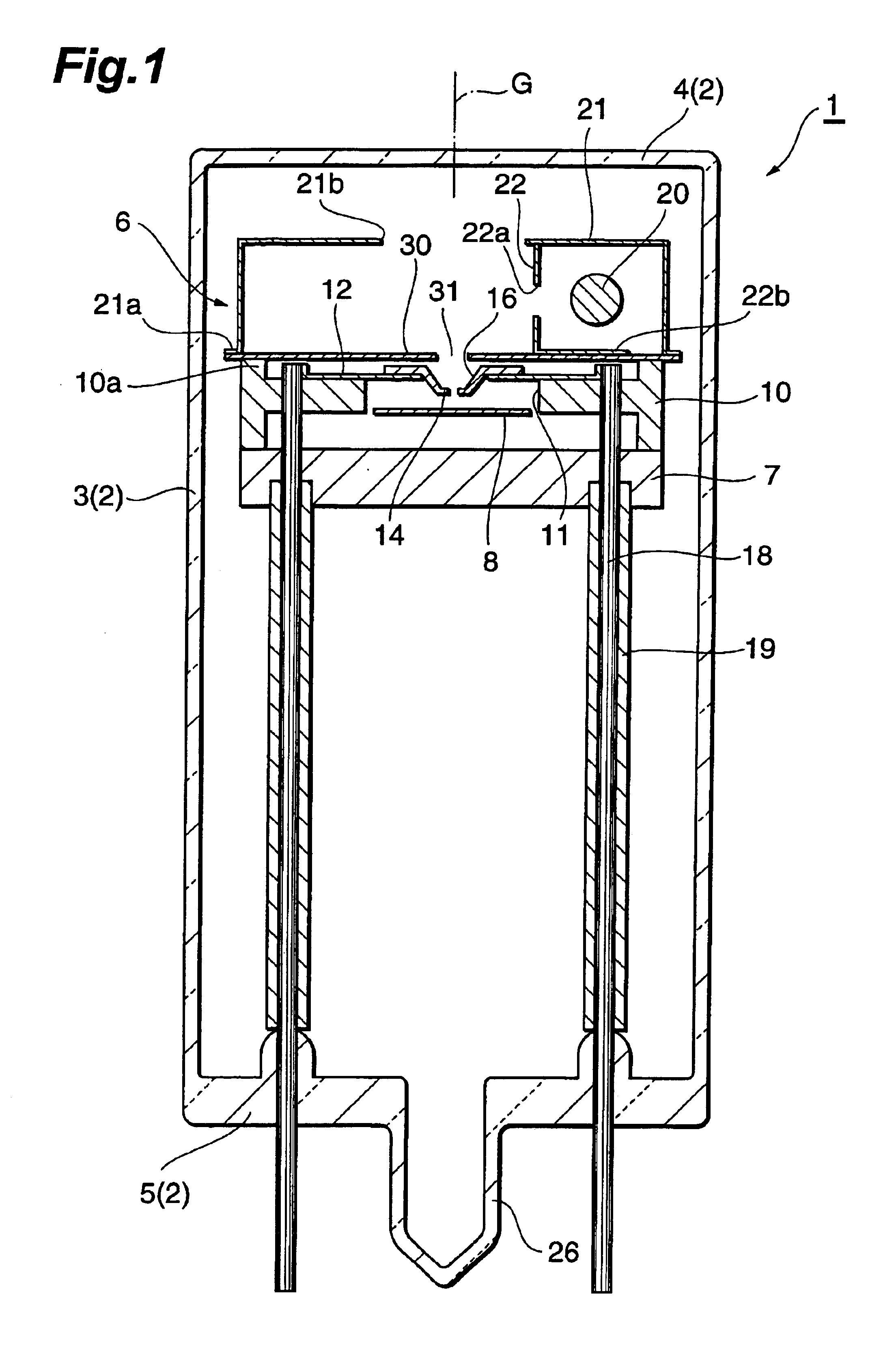
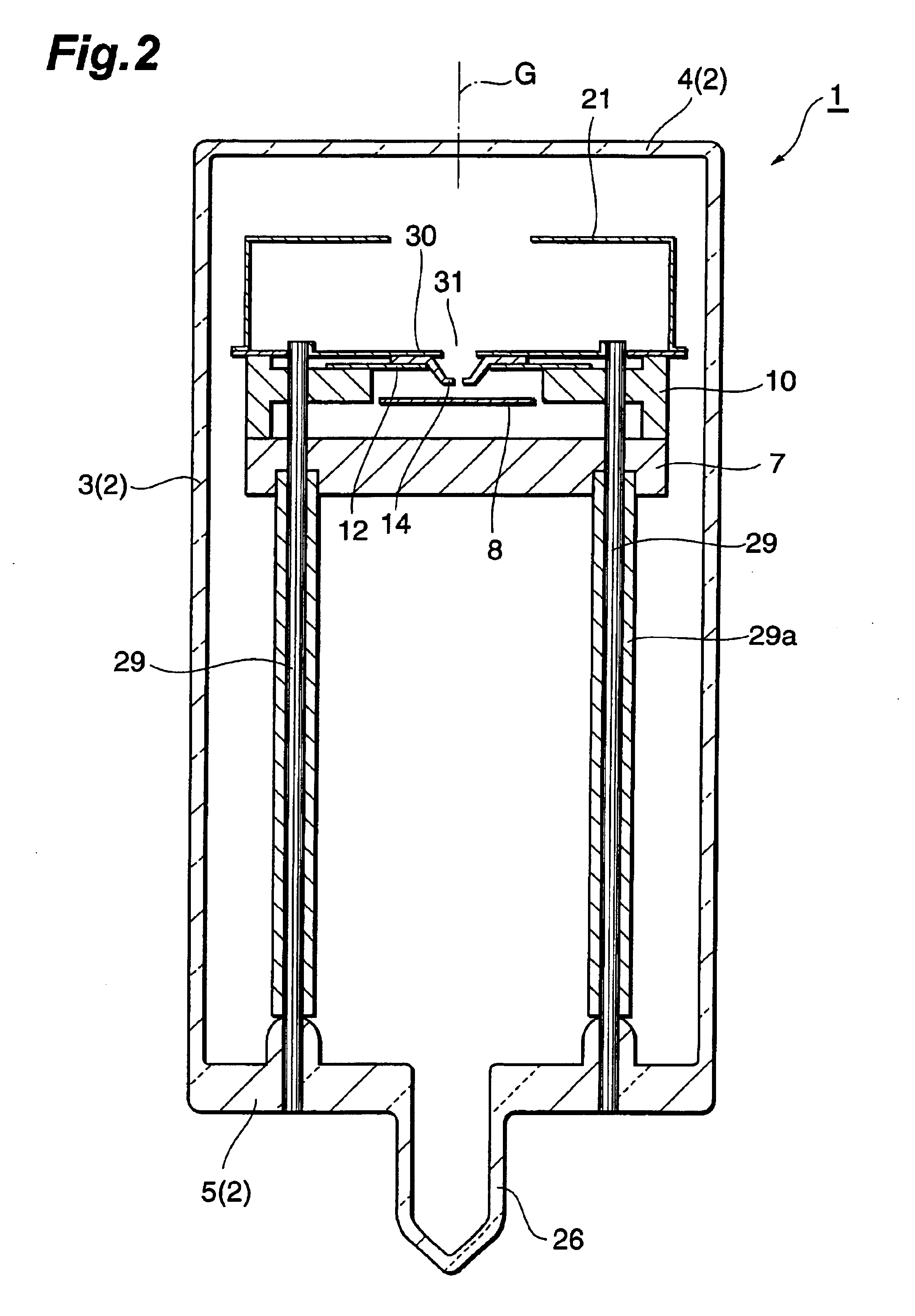
As shown in FIGS. 1 and 2, a gas discharge tube 1 is a head-on type deuterium lamp. The gas discharge tube 1 comprises a glass hermetically sealed container 2 into which deuterium gas is sealed at approximately several hundred Pa. The hermetically sealed container 2 is constituted by a cylindrical side tube 3, a light exit window 4 which seals one side of the side tube 3, and a stem 5 which seals the other side of the side tube 3. A light-emitting portion assembly 6 is housed inside the hermetically sealed container 2.
The light-emitting portion assembly 6 is provided with a disk-form base portion 7 made of an electrically insulating ceramic, and an anode plate (anode portion) 8 is supported on this base portion 7. The anode plate 8 is separated from the base portion 7 and electrically connected to respective distal end parts of stem pins (not shown) which are disposed in a standing position in the stem 5 so as to extend in the direction of a tube axis G.
The light-e...
second embodiment
(Second Embodiment)
As shown in FIG. 6, a gas discharge tube 40 is a side-on type deuterium lamp. This discharge tube 40 is provided with a glass hermetically sealed container 42 into which deuterium gas is sealed at approximately several hundred Pa. The hermetically sealed container 42 is constituted by a cylindrical side tube 43 which seals one end side thereof and a stem (not shown) which seals the other end side of the side tube 43. A part of the side tube 43 is used as a light exit window 44. A light-emitting portion assembly 46 is housed inside the hermetically sealed container 42.
The light-emitting portion assembly 46 comprises a base portion 47 made of an electrically insulating ceramic. An anode plate (anode portion) 48 is disposed in contact with the front face of the base portion 47, and the distal end part of a stem pin 49 disposed in a standing position in the stem so as to extend in the direction of the tube axis G is electrically connected to the back face of the anode...
third embodiment
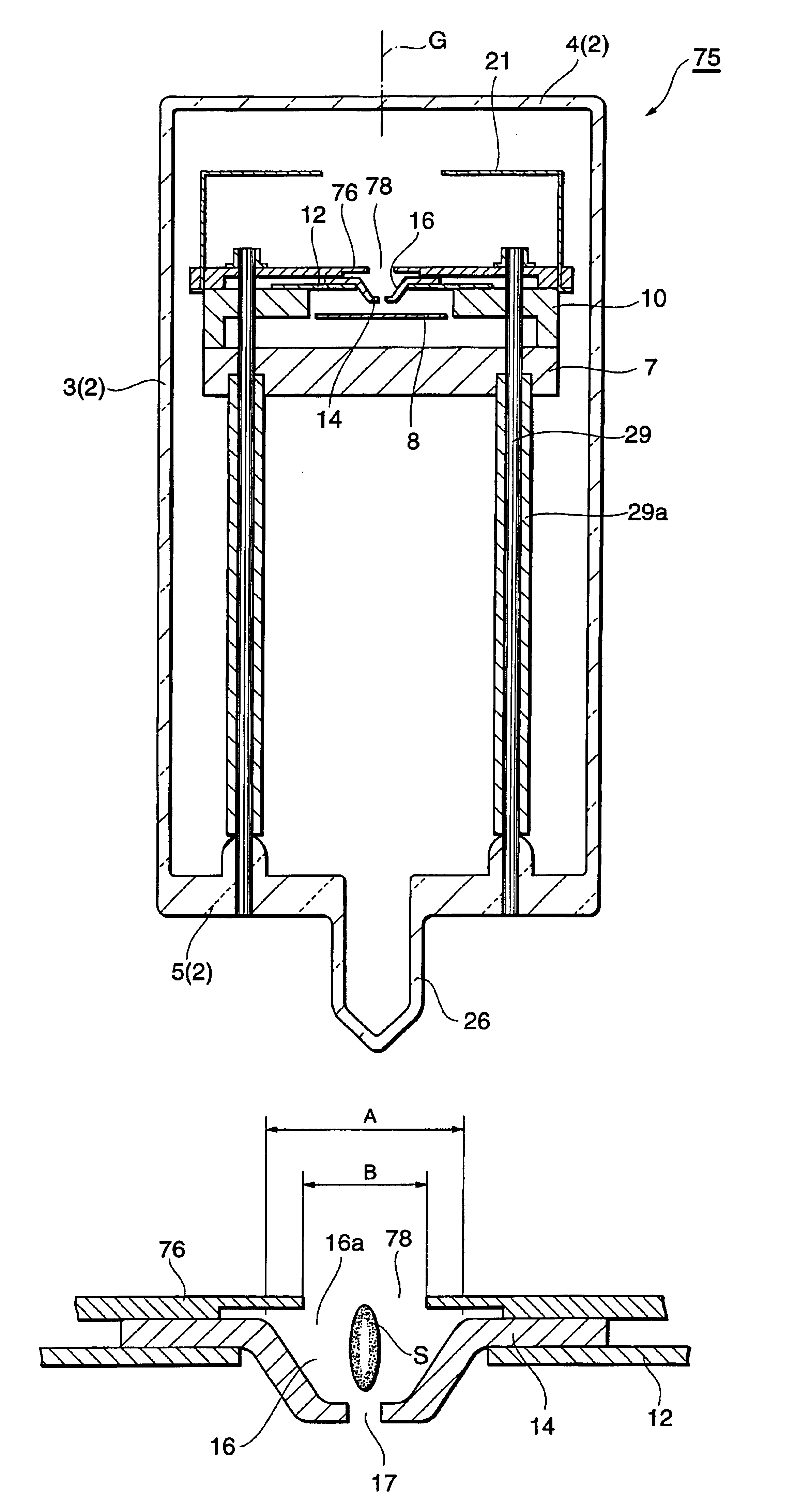
(Third Embodiment)
Next, another embodiment of the gas discharge tube will be described, but the description thereof will be limited to substantial differences with the first embodiment. Identical or similar constitutional components to the first embodiment have been allocated identical reference symbols and description thereof has been omitted.
As shown in FIGS. 7 to 9, a head-on type gas discharge tube 75 comprises a discharge limiting plate (discharge limiting portion) 76 made of an electrically insulating ceramic, and this discharge limiting plate 76 contacts the surface of a focusing electrode portion 14 and also contacts a focusing electrode support portion 10. Thus the discharge limiting plate 76 can be seated with stability on the focusing electrode support portion 10. By forming the discharge limiting plate 76 itself from a ceramic, electrical insulation between the focusing electrode portion 14 and discharge limiting plate 76, which are disposed in proximity, can be easily r...
PUM
 Abstract
Description
Claims
Application Information