Plasma generation and use of plasma generation apparatus

a technology of plasma generation apparatus and plasma, which is applied in the direction of plasma technique, energy-based chemical/physical/physicochemical process, disinfection, etc., to achieve the effect of reducing the efficiency and longevity of the apparatus, reducing the leaked electrical interference, and reducing the distance of leaked electrical fields

Active Publication Date: 2012-08-23
THE UNIV COURT OF THE UNIV OF GLASGOW
View PDF7 Cites 30 Cited by
  • Summary
  • Abstract
  • Description
  • Claims
  • Application Information

AI Technical Summary

Benefits of technology

[0040]It is possible for the second electrode not to be connected to ground but instead to have a signal applied to it. In this case, it is preferred that the signal has a predetermined phase relationship with the signal applied to the first electrode. For example, the signal applied to the second electrode may be exactly out of phase with the signal applied to the first electrode. Preferably, the magnitude of the signal applied to the second electrode is smaller than (and most preferably significantly smaller than) the magnitude of the signal applied to the first electrode. This allows the further reduction of leaked electrical interference from the device (i.e. reduction in the leaked electrical field at distances away from the device).
[0041]Preferably, the insulating layer interposed between the first electrode and the second electrode structure completely fills the space between the first electrode and the second electrode structure. This is advantageous because otherwise, if there were gas-filled spaces between the first electrode and the second electrode structure, a plasma may be generated in such spaces, which would reduce the efficiency and longevity of the apparatus.
[0042]In one particularly preferred configuration, the apparatus is suitable for treating a package. In this case, the forward surfaces of the of the second electrode portions and the forward surfaces of the gap portions together preferably form a package treatment surface. In use, the package to be treated is placed against the package treatment surface. The apparatus is then operable to generate plasma. Preferably, the generated plasma is then substantially wholly located inside the package to be treated. The significant advantage of this is that the product of the plasma (e.g. ozone) can be formed only inside the package, so that the user is not exposed to significant quantities of the product of the plasma.
[0043]Preferably, the package treatment surface and the package conform with each other in use in order to limit the size of gaps between the package treatment surface and the package. The limitation (or even elimination) of such gaps reduces the volume, external of the package, within which plasma can form.
[0044]Preferably, in use, at least a part of the package is overlaid over the whole of the second electrode structure. In this way, an area size of the part of the package that is conformed with the package treatment surface can be larger than the second electrode structure. This assists in ensuring that the plasma is generated only inside the package and not outside the package.

Problems solved by technology

The present inventors have realised that the prior art disclosures identified above each suffer from disadvantages, for example relating to safety of operation, ease of implementation and / or ease of use.

Method used


Image

  • Plasma generation and use of plasma generation apparatus
  • Plasma generation and use of plasma generation apparatus
  • Plasma generation and use of plasma generation apparatus

Examples


Embodiment Construction

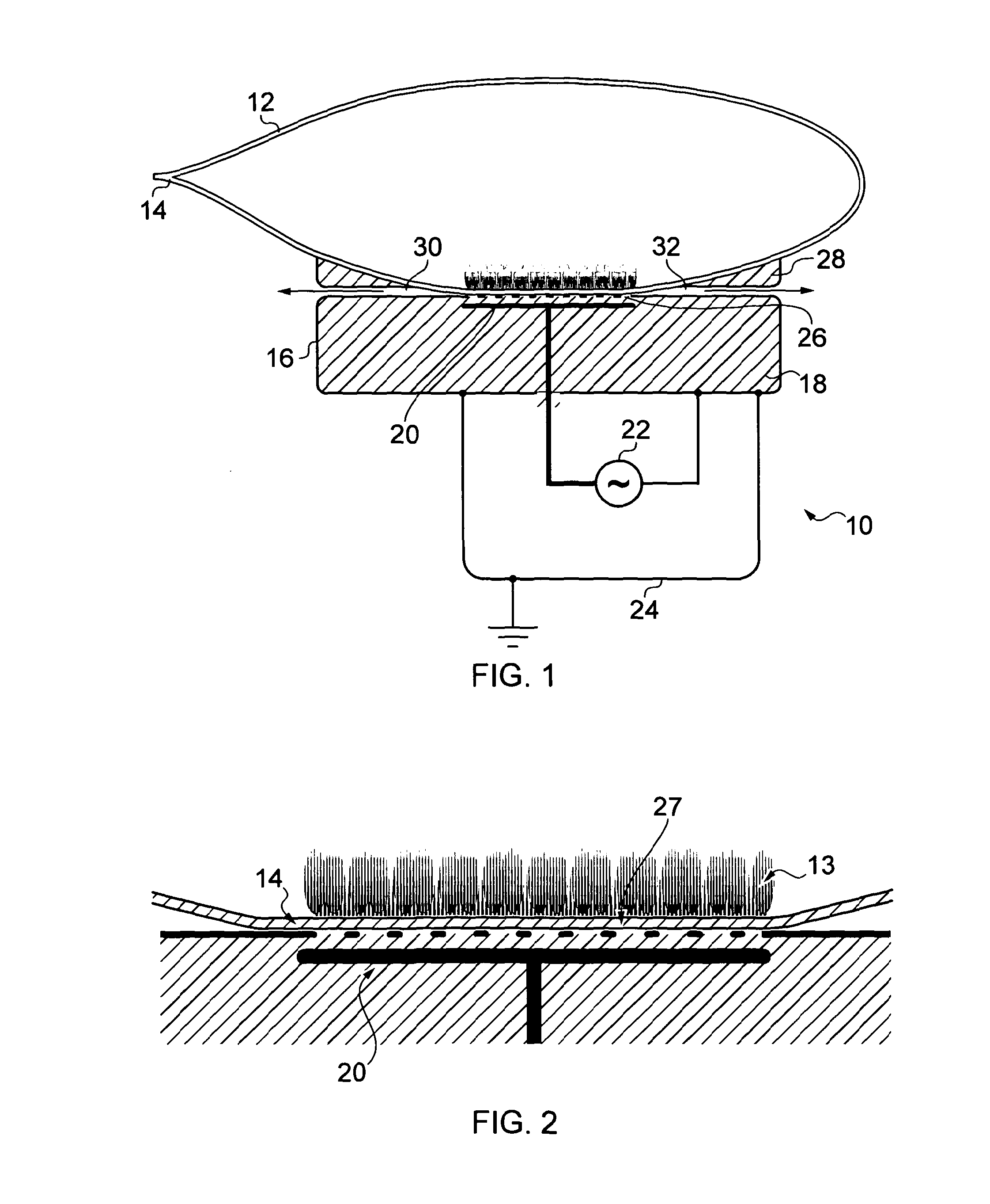
[0074]FIG. 1 shows a schematic cross sectional view of a sterilizing arrangement according to a preferred embodiment of the invention. The sterilizing arrangement includes a plasma generating apparatus 10 and a package 12 to be treated, including at least one object (not shown, but typically a foodstuff such as fresh fruit / vegetables or a medical product such as a wound dressing) contained in the package 12.

[0075]The package in this embodiment comprises a flexible bag formed of plastics material, such as PE. A seal 14 is formed in a known manner at a previously open region of the package.

[0076]The plasma generating apparatus 10 includes a housing 16 formed of metal and electrically connected, in use, to ground. Housing 16 encloses an insulator 18 embedded in which is a first, powered, electrode 20. First electrode 20 is electrically connected to a signal generation source, high voltage power supply 22. High voltage power supply 22 is fully contained within earthed metallic shell 24....


PUM

PropertyMeasurementUnit
heightaaaaaaaaaa
ac voltageaaaaaaaaaa
voltageaaaaaaaaaa

Abstract

A plasma generating apparatus comprises a first, powered electrode and a second electrode structure located in front of the first electrode. An insulating layer is interposed between the first electrode and the second electrode structure. The second electrode structure has a plurality of second electrode portions defining gap portions therebetween. The width of the gap portions is w. The second electrode portions each have a forward surface and the gap portions each having a forward surface, the height difference between the forward surface of each second electrode portion and the forward surfaces of the adjacent gap portions being h, and wherein h is at most 1 mm and the ratio w/h is at least 1. Thus, the forward surfaces of the second electrode portions and the forward surfaces of the gap portions together provide a smooth topography. The plasma generated by the apparatus (in air or other oxygen-containing gas) forms ozone, which can be used to treat foodstuffs, for example. The smooth topography allows substantially all of the plasma to be generated inside a package whose wall is pressed towards the second electrode structure.

Description

BACKGROUND OF THE INVENTION[0001]1. Field of the Invention[0002]The present invention relates to plasma generation apparatus and use of plasma generation apparatus. The invention has particular, but not exclusive, application to the sterilization of goods and / or surface decontamination.[0003]2. Related Art[0004]It is known that electrical discharges may be produced deliberately in order to provide useful effects. It is known, for example, to produce ozone (O3) using a corona discharge in air at atmospheric pressure. For example, U.S. Pat. No. 3,967,131 discloses a corona discharge ozone generating unit in which a corona discharge is generated between concentric electrodes separated by an air gap and a cylindrical dielectric (glass) shield and connected to an ac voltage of about 12,000 volts. The electrodes are formed from stainless steel mesh.[0005]A corona discharge is a form of plasma, i.e. a partially ionized gas, including a proportion of free electrons and ions, including excit...

Claims


Application Information

Patent Timeline
Patent Type & Authority Applications(United States)
IPC IPC(8): A61L2/03B01J19/08
CPCH05H1/24H05H1/2406A61L2/14A61L2/202H05H1/2418
Inventor DIVER, DECLAN ANDREWPOTTS, HUGH
Owner THE UNIV COURT OF THE UNIV OF GLASGOW
Why Eureka
Try Eureka