Single panel color video projection display using reflective banded color falling-raster illumination

a projection display and single-panel technology, applied in the field of projection displays, can solve the problems of loss of two-thirds the efficiency of a three-panel system, difficult and complicated prism manufacturing, and large system size and cos

Inactive Publication Date: 2005-03-22
SHARP LAB OF AMERICA INC
View PDF11 Cites 336 Cited by
  • Summary
  • Abstract
  • Description
  • Claims
  • Application Information

AI Technical Summary

Problems solved by technology

However, because of the necessity of having three panels, these systems tend to be larger and more expensive than the other option, which is a one-panel system illuminated with each of the three colors in sequence.
A disadvantage of this type of approach is that only one color is displayed at a time, resulting in a loss of two-thirds the efficiency of a three-panel system.
However, this makes the manufacture of the prisms much more difficult and complicated, increasing the costs.
However, this last approach requires large volume and decreases the efficiency of the optical system.
Additionally, the current art does not achieve uniform illumination across the panel, because the light bands change their dimensions due to variations in the path length of the illumination system to the image plane as the rotating prisms scan the light beam across the light valve.
Another difficulty lies in the positioning of the scanning prisms.
This requires relay optics, further raising the complexity of the system.

Method used


Image

  • Single panel color video projection display using reflective banded color falling-raster illumination
  • Single panel color video projection display using reflective banded color falling-raster illumination
  • Single panel color video projection display using reflective banded color falling-raster illumination

Examples


Embodiment Construction

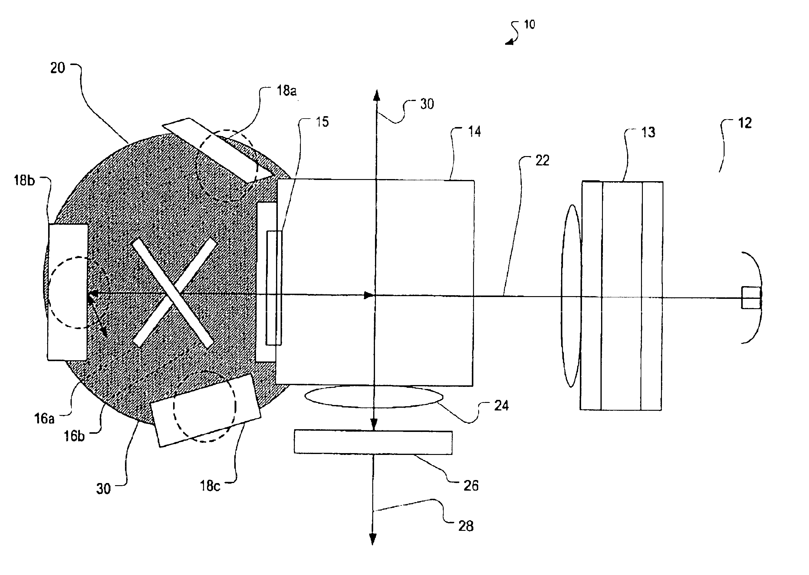
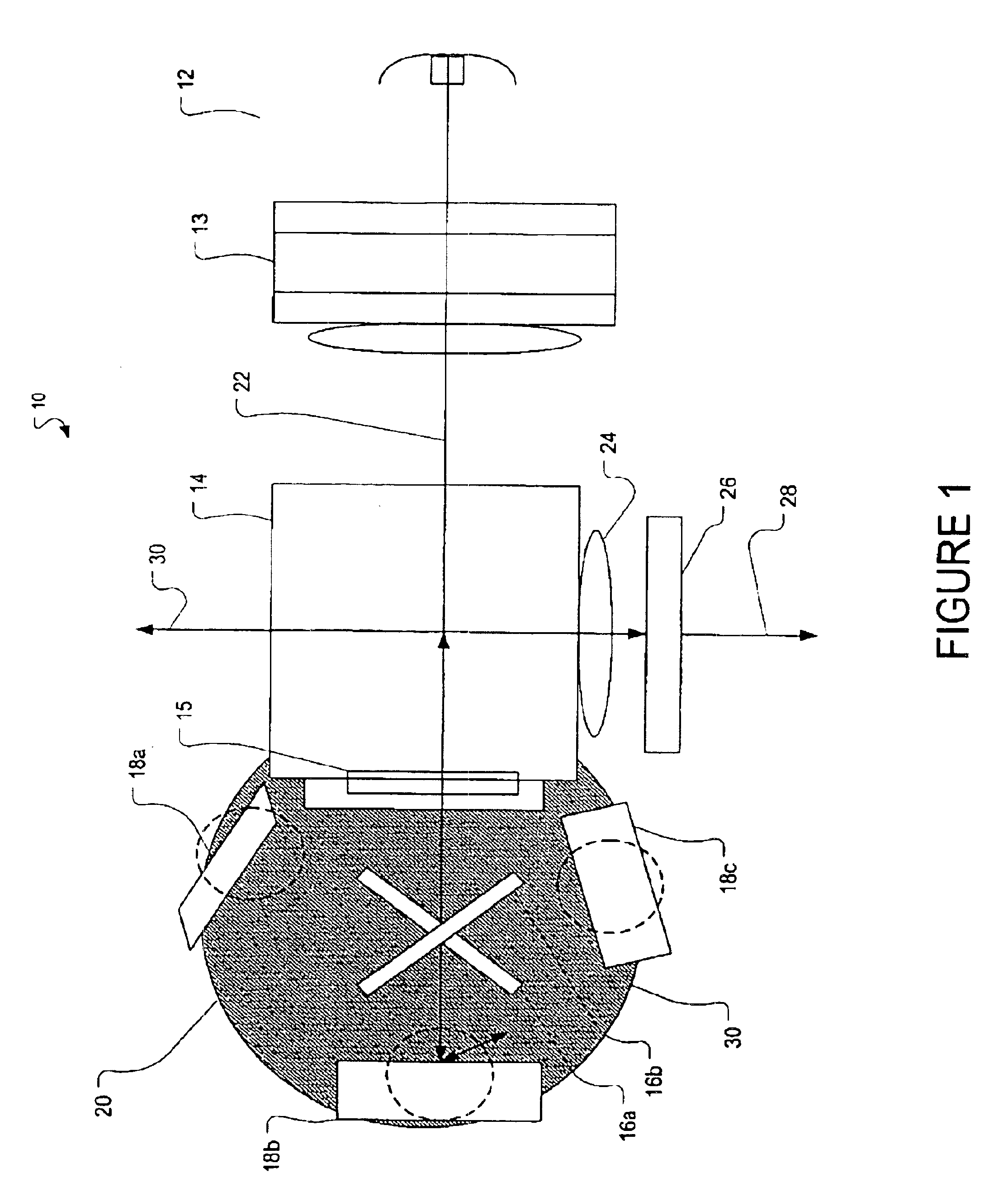
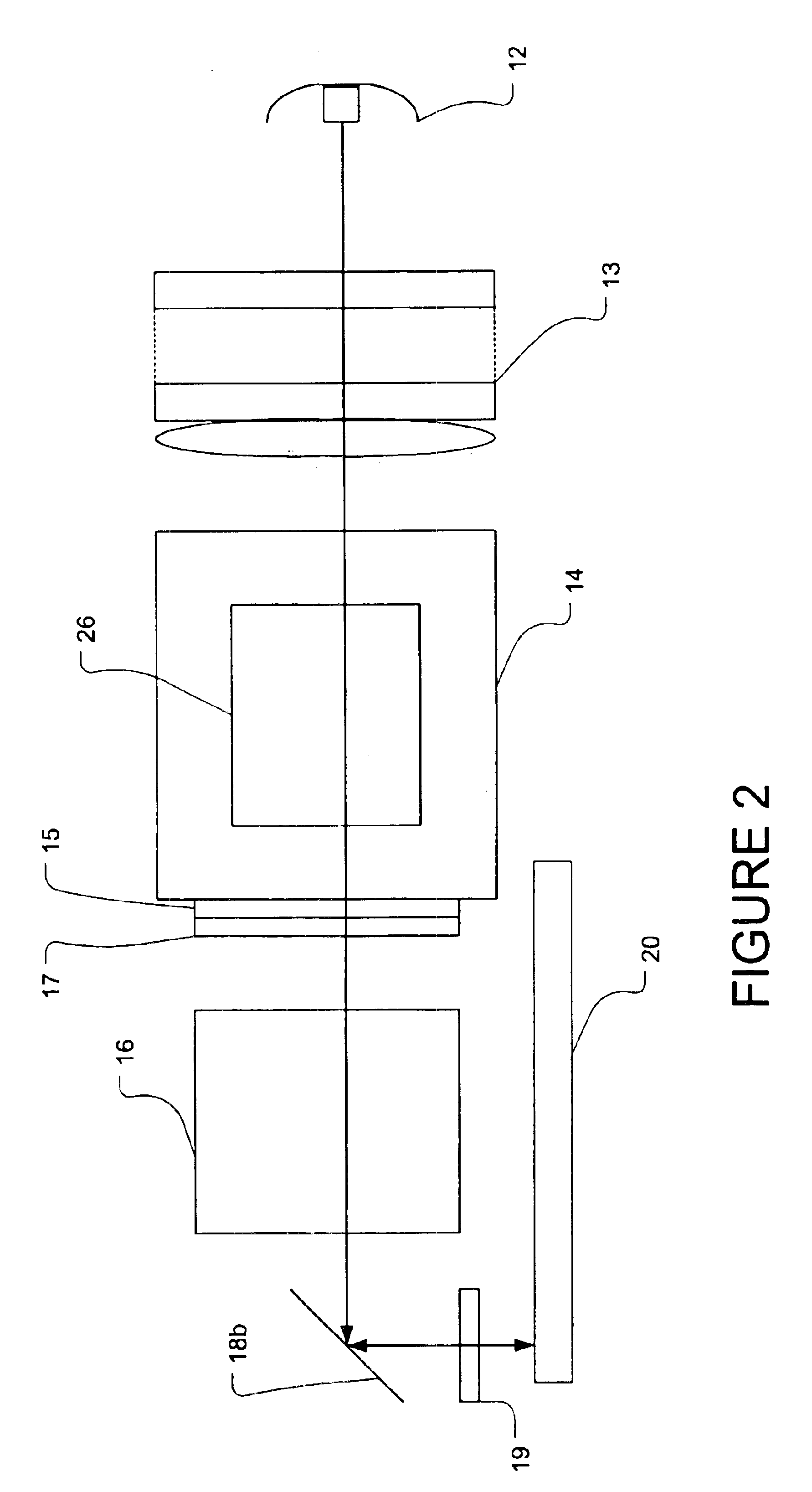
FIG. 1 shows one embodiment of a projection display system 10 in accordance with the invention. A light source 12 provides white light. A light integrator 13 shapes and homogenizes the light providing uniform illumination. The example shown in FIG. 1 could be used with light valves that require either polarized or unpolarized light. The projection display system shown in FIG. 1 uses a polarizing beam splitter 14 in conjunction with a quarter-wave (λ / 4) plate 15. The quarter wave plate converts the linearly polarized light exiting the polarizing beam splitter into circularly polarized light. For a display system not requiring polarized light, the beam of light would be randomly polarized and an air-gap prism could be used in place of the polarizing beam splitter.

After the light passes through the polarizing beam splitter, dichroic mirrors 16a and 16b split the light into red, green and blue paths with 120-degree angular separation. As will be discussed in more detail, it is possible ...


PUM

PropertyMeasurementUnit
tilt angleaaaaaaaaaa

Abstract

A projection display system. The projection system includes a light source, illumination optics that are capable of splitting the light from the source into individual color bands, and folding mirrors. The folding mirrors operate to direct the color bands to a reflective element that has a contoured surface. The contoured surface of the reflective element causes the light to form into scanning rasters that are recombined and sent to a spatial light modulator. The spatial light modulator is typically made up of a panel of individually addressable elements. If the spatial light modulator requires polarized light, a polarizing beam splitter and quarter-wave plate are included as part of the illumination optics.

Description

BACKGROUND1. FieldThis disclosure relates to projection displays, more particularly to projection displays using reflective banded color falling-raster illumination.2. BackgroundVideo projection displays using panels of light valves have undergone rapid growth and expansion in the past few years. These panels, such as liquid crystal displays (LCD) and digital micromirror devices (DMD), generally comprise arrays of individually addressable elements, such as an LCD cell or a mirror. The LCD-based panels may transmit light, where the light passes through the cell, or reflect the light, where the light bounces off of the cell or material directly behind the cell. Generally, except for some instances of image scaling, each element on the panel corresponds to a picture element (pixel) in the final image.In order to achieve color displays, the panel-based projection systems typically take one of two forms. In the first, one color panel is assigned to each of the traditional three display c...

Claims


Application Information

Patent Timeline
Patent Type & Authority Patents(United States)
IPC IPC(8): H04N9/31G02F1/13G02B27/28G02F1/1335G03B21/00
CPCH04N9/3197H04N9/3117
Inventor LI, LINSAMPSELL, JEFFREY BRIANSAROYA, JAGTAR SINGHVERNON, GEORGE STUART
Owner SHARP LAB OF AMERICA INC
Why Eureka
Try Eureka