Controlled transmission across packet network

a packet network and transmission control technology, applied in the field of packet communication, can solve problems such as shortchanging one or both telecommunication providers, not meeting network requirements, and adding to complexity

a packet network and transmission control technology, applied in the field of packet communication, can solve problems such as shortchanging one or both telecommunication providers, not meeting network requirements, and adding to complexity

US6870841B1Inactive Publication Date: 2005-03-22AT&T INTPROP II L P

Image

  • Controlled transmission across packet network
  • Controlled transmission across packet network
  • Controlled transmission across packet network

Examples


Embodiment Construction

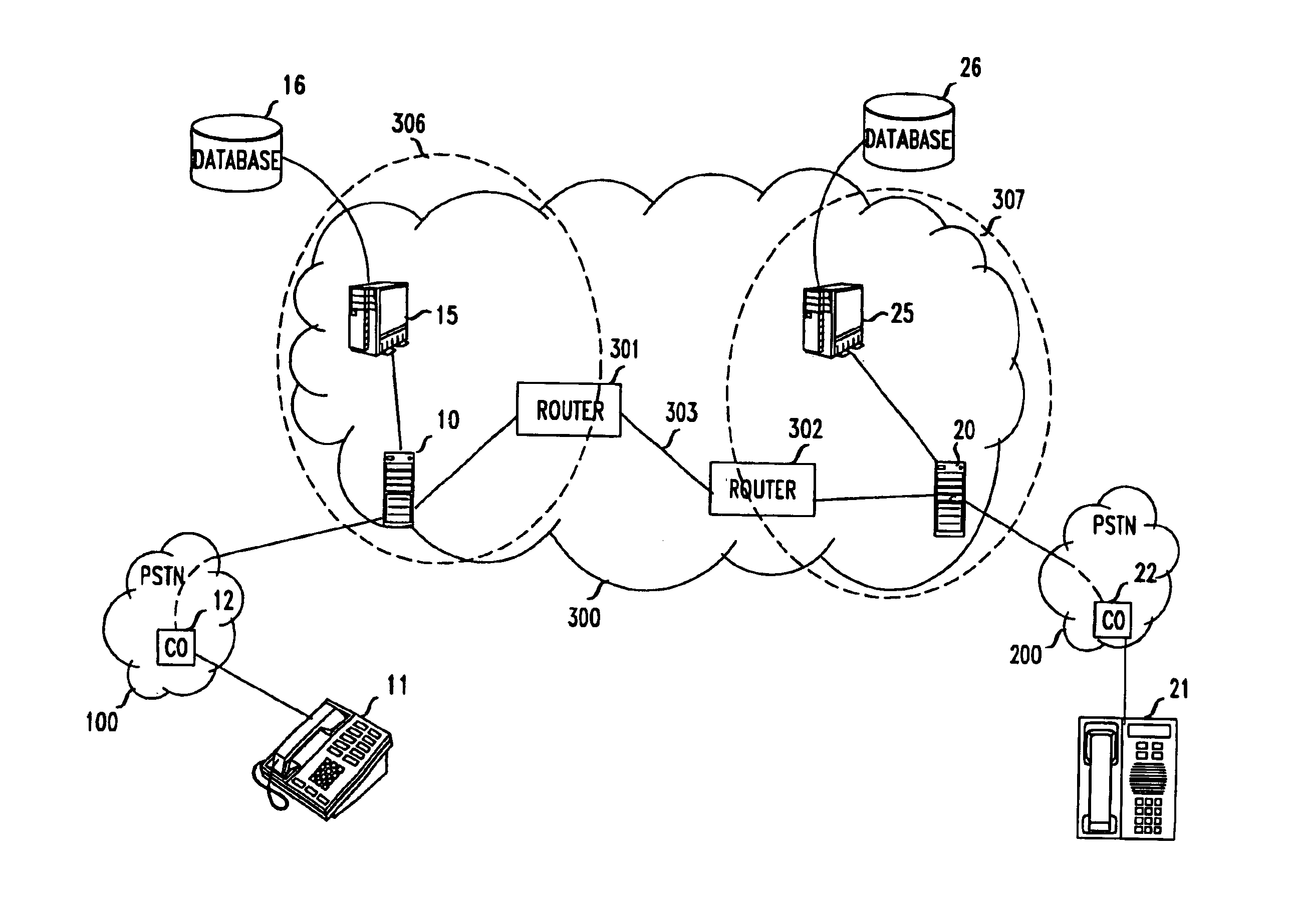
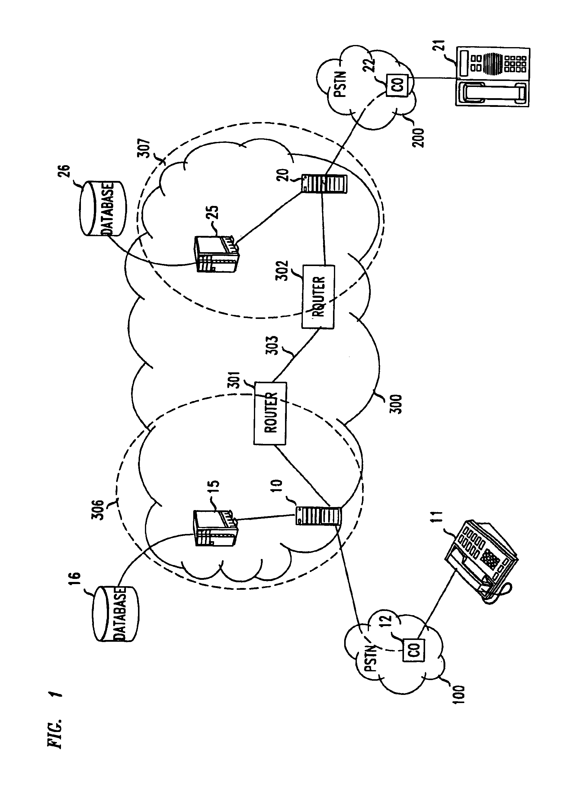
FIG. 3 illustrates a packet network arrangement that comports with the principles of this invention; and with respect to those principles, it is similar to the FIG. 1 arrangement. For illustrative purposes, however, instead of a single network as shown in FIG. 1, FIG. 3 depicts an ATM network 310, and an ATM network 320; instead of gateway 10, PSTN 100 and user 11, there is an MTA 13 that is connected to switch 314 within network 310; and instead of gateway 20, PSTN 200 and user 12, there is an MTA 23 that is connected to switch 324 within network 320.

It is noted that the switches in ATM networks perform essentially the same function as do the routers in IP networks. In this disclosure, therefore, the term “node” is used to subsume both a router and a switch.

For convenience, it may be assumed that MTA 13 is in New York and network 310 is owned by Verizon, that MTA 23 is in Los Angeles and network 320 is owned by PacTel, and that the connection between networks 310 and 320 is either ...


PUM


Abstract

Control over the movement of packets is exercised by edge nodes of a network mapping the addresses of incoming packets in accordance with a prespecified functional mapping P. Remote sources of packets are provided address information that is mapped with a prespecified functional mapping Q, where mappings P and Q are such that P(Q(j)=j. The mapping change at regular intervals, or upon the occurrence of specified events, and with each change, the communicating the remote source is provided with a different mapped address to be used.

Description

BACKGROUNDThis invention relates to packet communication and, more particularly, to fee-based communication across multiple packet networks.Most US telecommunication providers currently employ packet networks to transport both voice and-data signals. Such a network, shown in FIG. 1, transports information in packets that are routed from router to router (e.g. from router 301 to router 302), via links (e.g., 303), from an originating point in the network to a terminating point in the network.FIG. 1 depicts a typical arrangement for coupling a user 11 in one location (for example, New York) to a user 12 in another location (for example, Los Angeles). User 11 is connected to a local circuit-switched network 100 in New York (e.g., Verizon), and more particularly to a central office 12 within network 100. Similarly, user 21 is connected to a local circuit-switched network 200 in Los Angeles (e.g., PacTel), and more particularly to a central office 22 within network 200.When a call from u...

Claims


Application Information

Patent Timeline
22 Mar 2005
Publication
US6870841B1
IPC
H04L29/06; H04L29/12
CPC
H04L29/06; H04L29/12009; H04L29/12433; H04L65/80; H04L61/2539; H04L61/35; H04L29/12783; H04L29/06027
Inventors
BROWN, JOHN CARL; RUSSELL, LARRY ARNISE