High-efficiency encoder and video information recording/reproducing apparatus

a video information and encoder technology, applied in the field of digital signal recording/reproducing apparatus, can solve the problems of deteriorating image quality immediately after scene change, increasing the total amount of codes, increasing the size of hardware, etc., and reducing the hardware size

Inactive Publication Date: 2005-03-22
MITSUBISHI ELECTRIC CORP
View PDF27 Cites 11 Cited by
  • Summary
  • Abstract
  • Description
  • Claims
  • Application Information

AI Technical Summary

Benefits of technology

[0045]It is an object of the invention to provide a high-efficiency encoder which does not perform motion-compensation on an intra-field (or intra-frame) every n fields (or n fram...

Problems solved by technology

Therefore, there arise following problems in the above-described conventional predictive method.
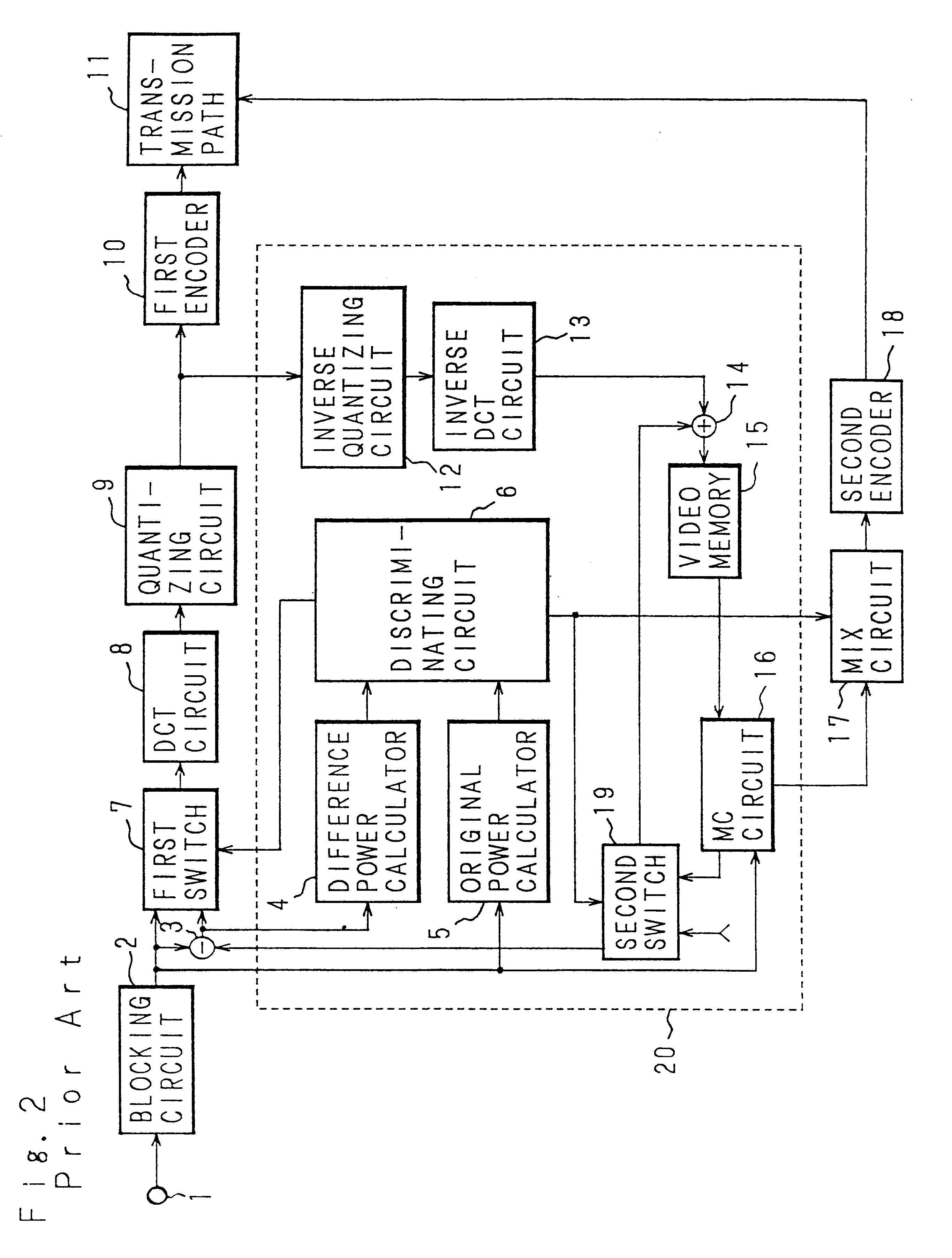
In such a predictive method, since motion-compensation prediction is performed using the video data of the one preceding field or frame, there arises a first problem that the capacity of the field memory or frame memory is increased and the hardware is enlarged in size.
In the conventional predictive method, when a scene change once occurs in the unit of frame, it is difficult during encoding of the image after the scene change to perform the compression according to motion-compensation prediction from the reference picture which was obtained before the scene change, thereby causing a second problem that the total amount of codes is increased.
4 and 5), there is a third problem that, when a scene change occurs in a step of a motion-compensation prediction process, the quality of the image immediately after the scene change is deteriorated.
This problem is caused, owing to the scene change, by motion-compensation prediction which unsatisfactorily performs time correlation is, thereby increasing the information amount being generated.
Although there is no great deterioration in the portion of the scene change, the decrease of the information amou...

Method used


Image

  • High-efficiency encoder and video information recording/reproducing apparatus
  • High-efficiency encoder and video information recording/reproducing apparatus
  • High-efficiency encoder and video information recording/reproducing apparatus

Examples


embodiment 1

[0108

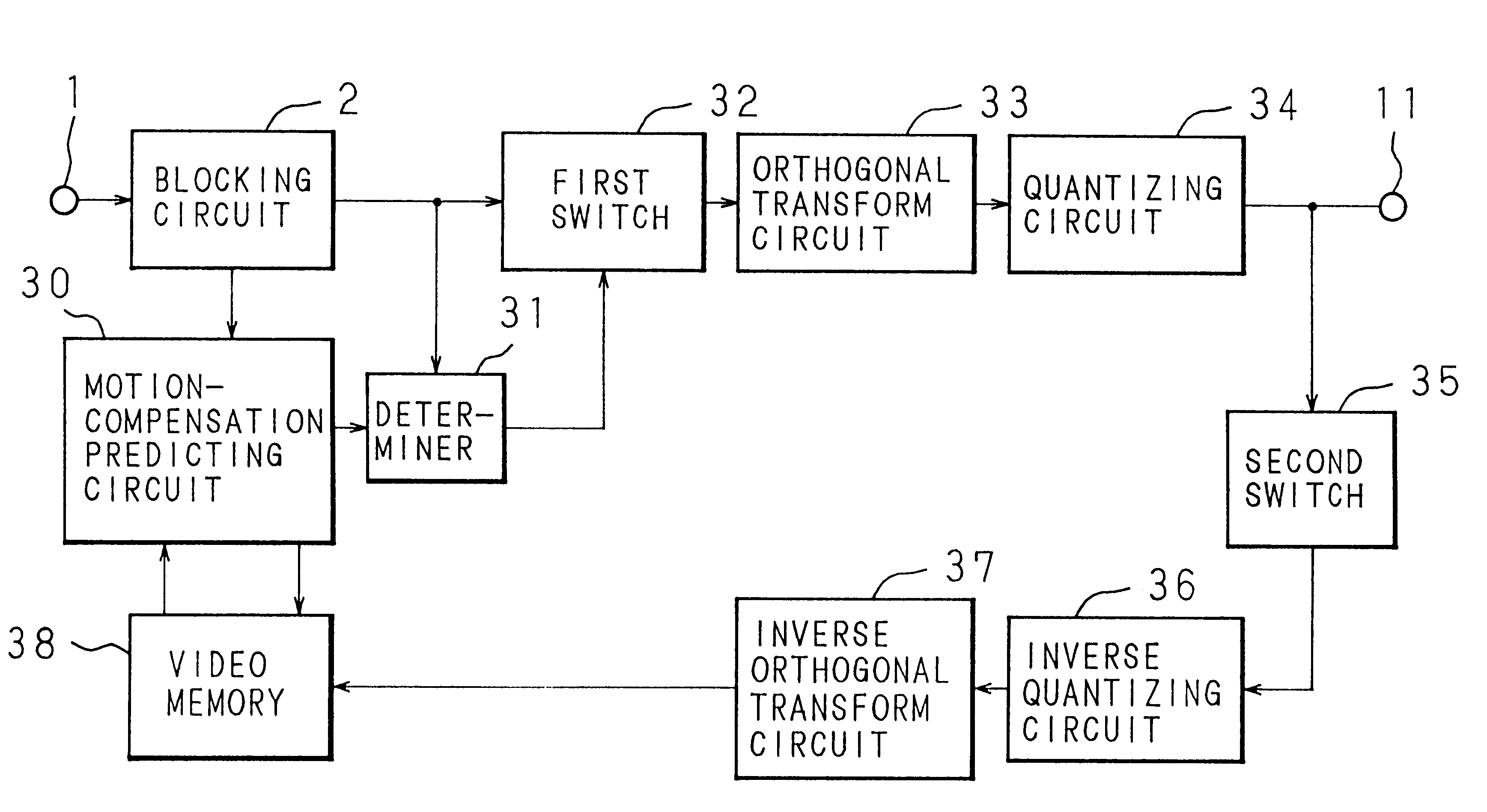
[0109]Hereinafter, a first embodiment of the present invention will be described with reference to the drawings. FIG. 25 is a block diagram illustrating the first embodiment of the invention. In FIG. 25, 1 designates an input terminal for a digital video signal, 2 designates a blocking circuit, which forms into a block a digital video signal input through the digital video signal input terminal 1, 30 designates a motion-compensation predicting circuit which performs motion-compensation prediction between the block output from the blocking circuit 2 and an intra-field and outputs a difference signal between an input block and a prediction block, 31 designates a determiner which selects the one having the smaller sum of absolute values between the input signal from the blocking circuit 2 and a prediction difference signal from the motion-compensation predicting circuit 30, 32 designates a first switch which selectively outputs encoded blocks output from the blocking circuit 2 and...

embodiment 2

[0115

[0116]According to Embodiment 1 described above, in the determiner 31, the output having the smaller sum of absolute values is selected from the outputs of the blocking circuit 2 and motion-compensation predicting circuit 30, to be output to the first switch 32. In a field where determiner 31 selects the forced intra mode more frequently than the prediction mode, it may be judged that a scene change has occurred in the field, and assuming that the whole field is in the intra mode encoding may be performed. An embodiment constructed so as to perform this operation is Embodiment 2 described below.

[0117]FIG. 27 is a block diagram showing the configuration of the second embodiment. In the figure, 40 designates a determiner which selects the one having the smaller sum of absolute values, from an input block from the blocking circuit 2 and a prediction difference block from the motion-compensation predicting circuit 30, and which judges a field where the input block from the blocking...

embodiment 3

[0123

[0124]FIG. 31 is a block diagram showing the configuration of a high-efficiency encoder in Embodiment 3. In FIGS. 31, 1-14 and 16-20 designate the elements identical to those of the apparatus in FIG. 2. The reference numeral 50 designates a mode counter which counts the number of blocks of the intra mode, 51 designates a direction switching circuit which compares a predetermined number of blocks with the number of blocks of the intra mode output from the mode counter and which determines the reference picture for the next field, and 52 designates a video memory which stores output blocks in order to perform motion-compensation prediction and which outputs the reference picture for the next field as the search range.

[0125]Then, the operation will be described. Irrespective of an intra-field or a prediction-field, input digital video signals are segmented by the blocking circuit 2 into input blocks, a unit of which consists of m [pixels]×n [lines]. In order to obtain a difference...


PUM


Abstract

In a high-efficiency encoder which performs motion-compensation prediction, an intra-field is set every n fields. The presence of a scene change is detected. When a scene change occurs, a reference picture of motion-compensation prediction is switched, or the field immediately after the scene change is set as an intra-field.

Description

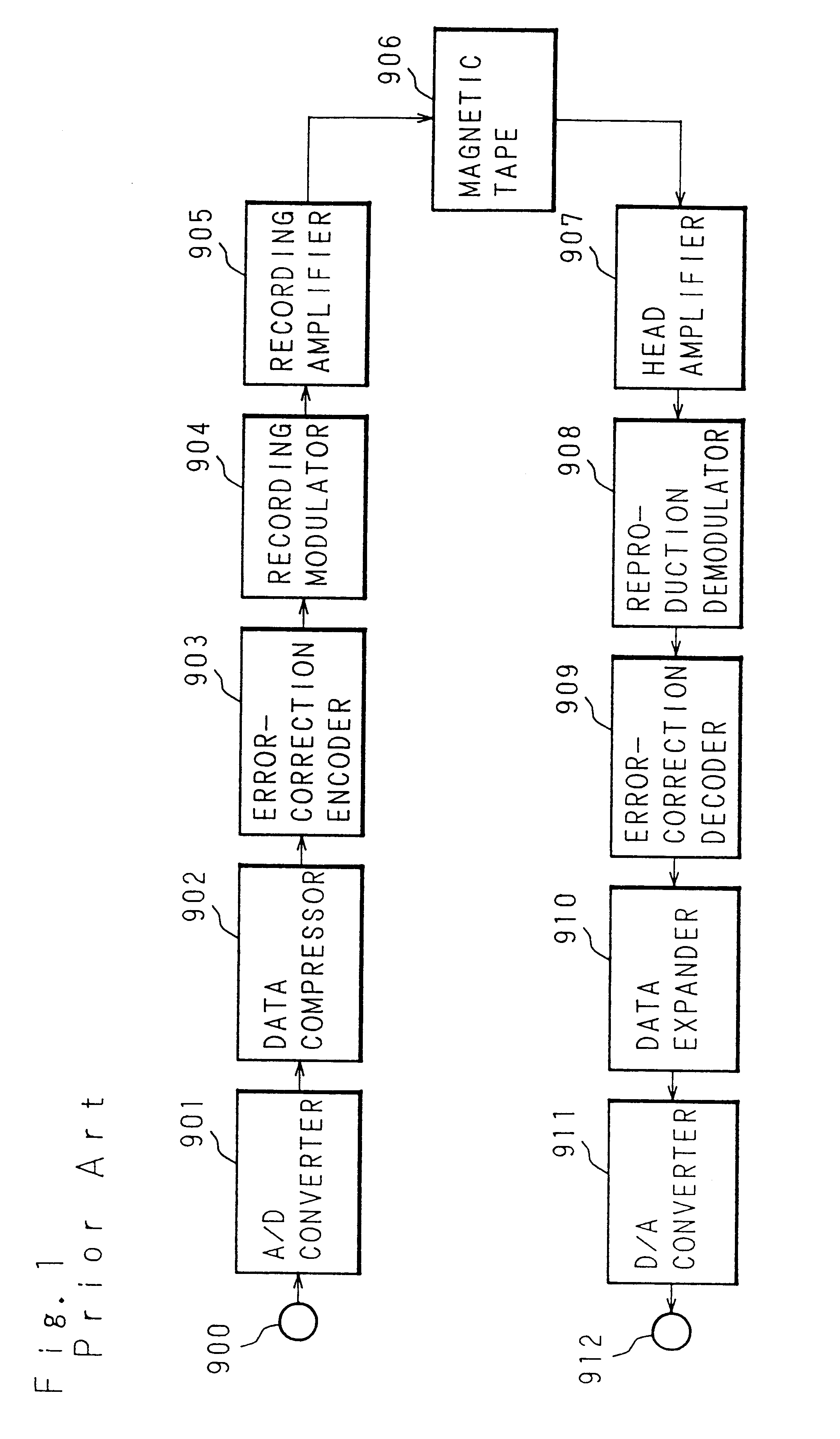
[0002]This application is a divisional of application Ser. No. 09 / 113,287, filed on Jul. 10, 1998 now U.S. Pat. No. 5,909,252, which is a divisional of application Ser. No. 08 / 559,488 filed on Nov. 15, 1995 now U.S. Pat. No. 5,841,474, which is a divisional of application Ser. No. 08 / 011,243 filed on Jan. 29, 1993 now U.S. Pat. No. 5,479,264, the entire contents of which are hereby incorporated by reference.BACKGROUND OF THE INVENTION[0003]1. Field of the Invention[0004]This invention relates to a digital signal recording / reproducing apparatus such as a video tape recorder (hereinafter, abbreviated as “VTR”), a video disk player and an audio tape recorder in which video and audio signals are recorded and reproduced in the digital form, and particularly to an apparatus which performs motion-compensation prediction on a video signal for compression-encoding.[0005]2. Description of the Related Art[0006]In a digital VTR for home use, data compression is indispensable in view of cost and...

Claims


Application Information

Patent Timeline
IPC IPC(8): G11B27/28G11B27/032G06T9/00G11B27/036G11B27/031H04N7/24H04N7/36H04N5/926H04N7/26H04N7/50H04N7/52H04N9/804H04N7/46H04N5/928H04N9/806H04N9/82H04N9/835H04N9/83H04N5/7824H04N5/7826
CPCG11B20/00007H04N19/577G11B27/032G11B27/036G11B27/28H04N5/9262H04N5/9264H04N9/8042H04N19/105H04N19/503H04N19/172H04N19/46H04N19/115H04N19/61H04N19/107H04N19/114H04N19/136H04N19/137H04N19/142H04N19/18H04N19/177H04N19/179H04N19/42H04N19/87G11B2220/20G11B2220/90G11B2220/91H04N5/78263H04N5/78266H04N5/928H04N7/012H04N9/8063H04N9/83H04N9/8355G11B27/005
Inventor UEDA, TOMOHIROITOW, TAKASHIASAMURA, YOSHINORIONISHI, KENMISHIMA, HIDETOSHI
Owner MITSUBISHI ELECTRIC CORP
Why Eureka
Try Eureka