Electroacoustic transducer, process of producing the same and electroacoustic transducing device using the same

a technology of electroacoustic transducers and transducers, applied in the direction of transducers, electrical transducers, and magnetic electrostatic transducers, can solve the problems of difficulty in controlling the thickness of oscillation films, inability to obtain sufficient acoustic characteristics, and limited frequency characteristics within a certain range, so as to achieve good acoustic characteristics

Inactive Publication Date: 2005-03-22
SHARP KK
View PDF8 Cites 59 Cited by
  • Summary
  • Abstract
  • Description
  • Claims
  • Application Information

AI Technical Summary

Benefits of technology

In view of the above-described circumstances, an object of the present invention is to provide an electroacoustic transducer which provides an easy control of the thickness of the oscillation film, one electrode of the capacitor, ensures an appropriate tension for the oscillation film and therefore exhibits good acoustic characteristics, and its production process.

Problems solved by technology

However, the capacitor with the above-described structure has the problem of difficulty in controlling the thickness of the oscillation film 82 since the oscillation film 82 which is one electrode is formed through thinning the semiconductor substrate 81 by etching.
For this reason, if this pressure sensor is applied to a capacitor for generating electric signals equivalent to acoustic signals, frequency characteristics are limited within a certain range.
Accordingly sufficient acoustic characteristics cannot be obtained, and electric signals equivalent to acoustic signals themselves cannot be generated.
Therefore, the capacitor cannot be applied to an electroacoustic transducer such as a microphone or the like.
Thus the acoustic characteristics deteriorate.

Method used


Image

  • Electroacoustic transducer, process of producing the same and electroacoustic transducing device using the same
  • Electroacoustic transducer, process of producing the same and electroacoustic transducing device using the same
  • Electroacoustic transducer, process of producing the same and electroacoustic transducing device using the same

Examples


first embodiment

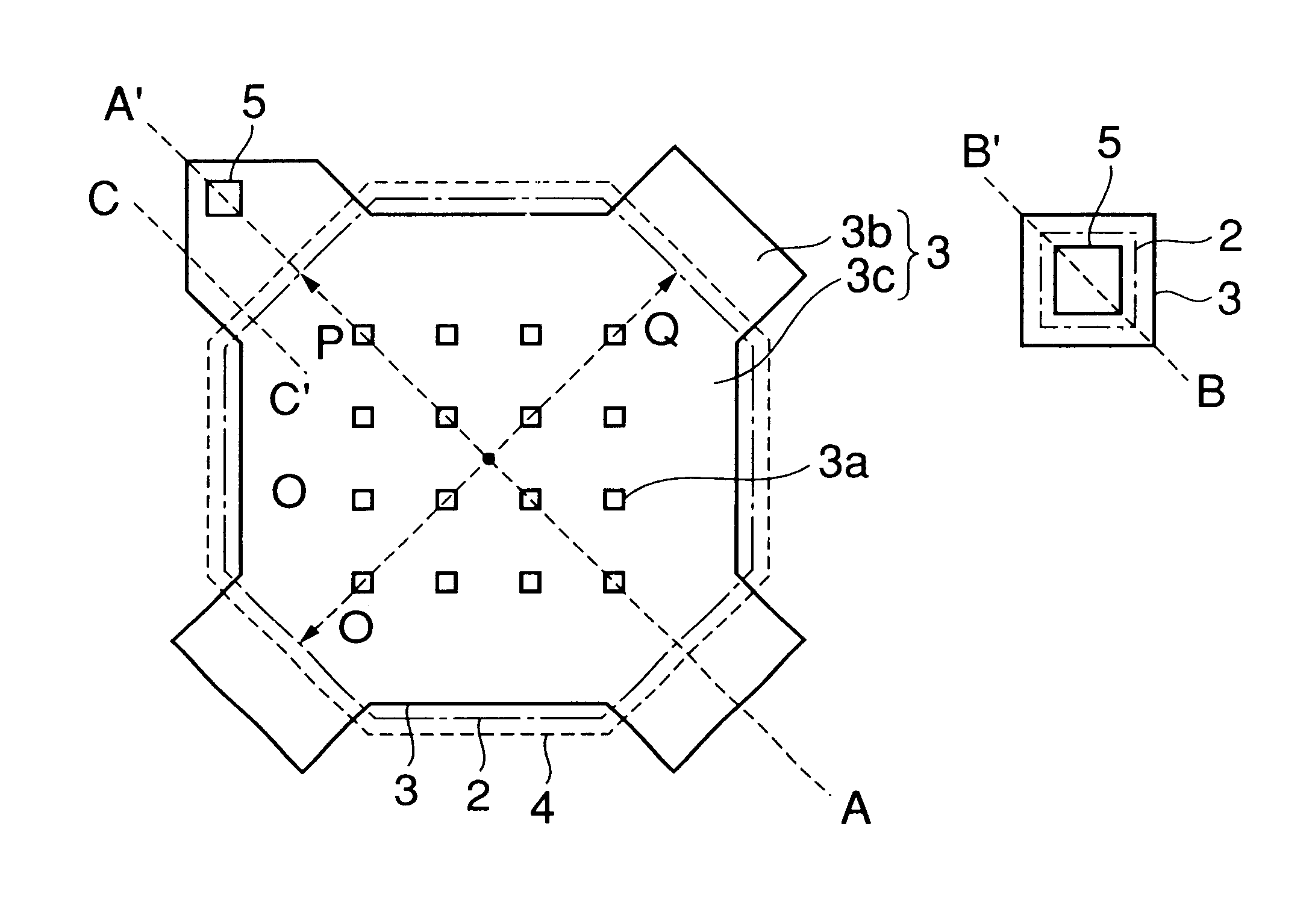
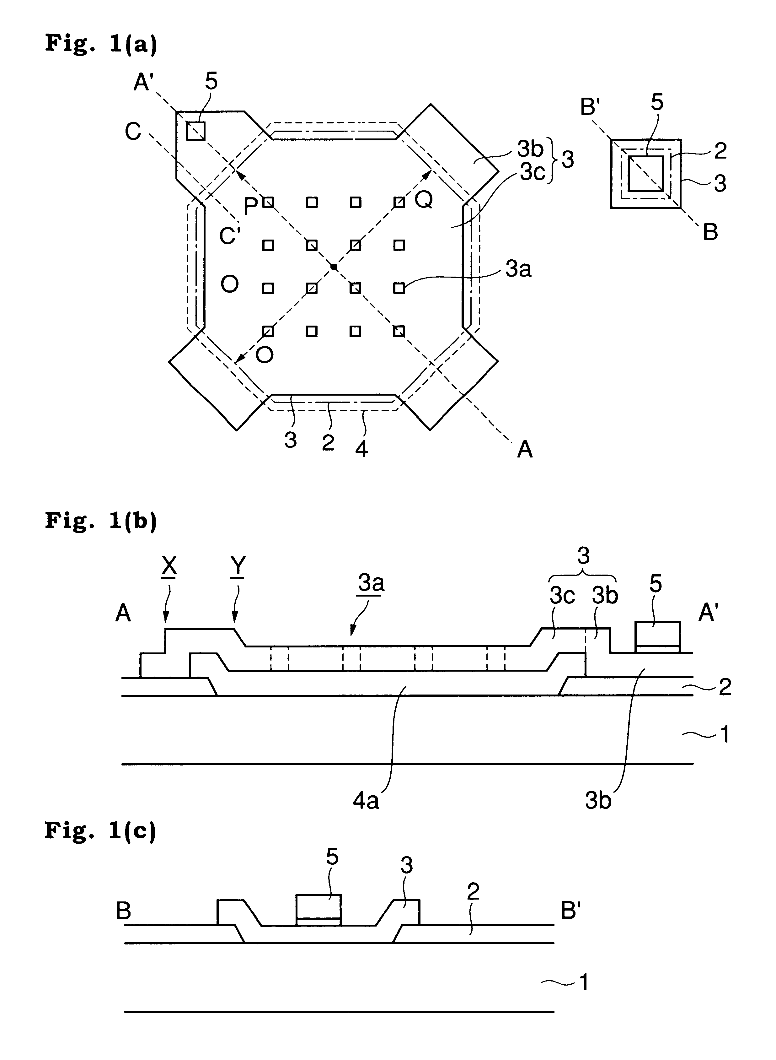
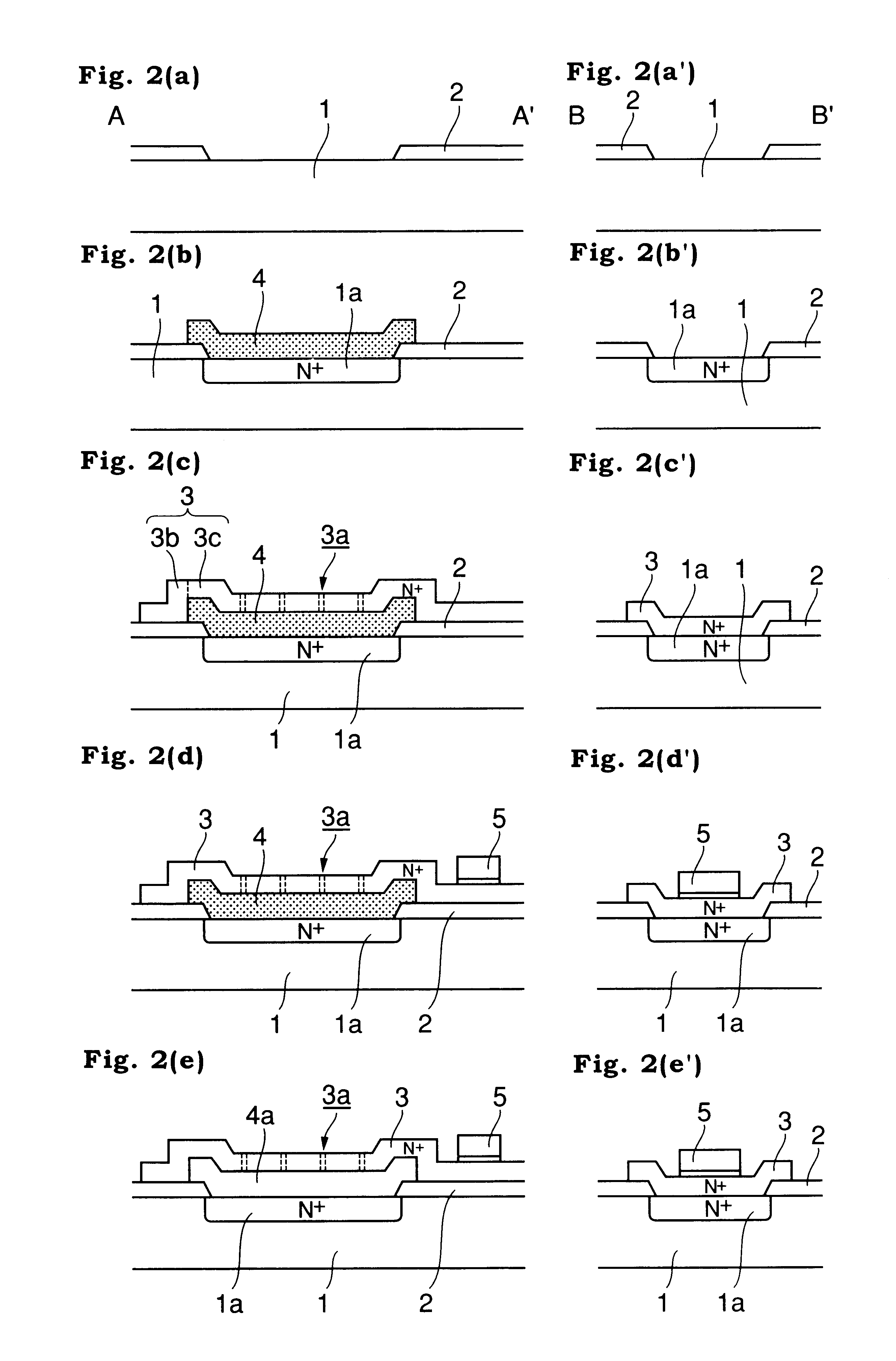
As shown in FIG. 1(a) to 1(c), the electroacoustic transducer of this embodiment is composed of a lower electrode formed of a silicon substrate 1, an upper electrode formed of a polysilicon film 3 including an oscillation portion 3c and support portions 3b extended from four places on the periphery of the oscillation portion 3c, a cavity 4a formed between the lower electrode and the upper electrode, and an insulating layer of a SiN film 2 disposed between the lower electrode and the upper electrode. The insulating layer, as indicated by an alternate long and short dash line in FIG. 1(a), covers almost the entire surface of the silicon substrate 1 except that it has openings almost immediately under the oscillation portion 3c of the upper electrode and in a region for connecting a terminal to the lower electrode.

The oscillation portion 3c of the upper electrode is in the shape of a substantially equilateral octagon, and the distances O, P and Q from its center to the support portions...

second embodiment

As shown in FIG. 6, an electroacoustic transducer in this embodiment is substantially the same as the electroacoustic transducer in FIG. 1 except that in a polysilicon film 13 forming the upper electrode, the bottom face of an oscillation portion 13c (a part of the upper electrode immediately above a cavity 14a) is above the top face of a support portion 13b extended immediately above an insulating layer of a SiN film 2.

third embodiment

As shown in FIG. 7, an electroacoustic transducer in this embodiment is substantially the same as the electroacoustic transducer in FIG. 1 except that an insulating layer of an SiN film 22 covers the entire surface of a silicon substrate 1 serving as a lower electrode and consequently an upper electrode has an up and down Z only at a support portion 23b.

In this electroacoustic transducer, since the insulating layer covers the entire surface of the lower electrode, the electroacoustic transducer can prevent short circuit between the upper electrode and the lower electrode even if a sudden large sound gives oscillation when the electroacoustic transducer is used as an electroacoustic transducer. Accordingly, it is possible to avoid damage to or breakdown of the electroacoustic transducer itself.


PUM


Abstract

An electroacoustic transducer comprises: a lower electrode; an upper electrode including an oscillation portion and a support portion for supporting the oscillation portion at least at a part of a periphery of the oscillation portion; and an insulating layer for insulating the lower electrode from the upper electrode, wherein the upper electrode has an up and down in the oscillation portion and/or in the support portion to provide a cavity between the upper electrode and the lower electrode.

Description

CROSS-REFERENCES TO RELATED APPLICATIONSThis application is related to Japanese Patent Applications Nos. H11(1999)-350277 and 2000-231329, filed on Dec. 9, 1999 and Jul. 31, 2000 whose priorities are claimed under 35 USC § 119, the disclosures of which are incorporated by reference in their entirety.BACKGROUND OF THE INVENTION1. Field of the InventionThe present invention relates to an electroacoustic transducer, a process of producing the same and an electroacoustic transducing device using the same.2. Description of Related ArtThere have been proposed semiconductor devices in which capacitors capable of functioning as electroacoustic transducers such as microphones are integrated in semiconductor chips (see W084 / 03410, for example).As shown in FIG. 21(e), such a capacitor is composed of an oscillation film 82 serving as one electrode of the capacitor which film is formed on a semiconductor substrate 81 having a cavity 81a, a support portion 83 of a silicon nitride film for ensurin...

Claims


Application Information

Patent Timeline
Patent Type & Authority Patents(United States)
IPC IPC(8): H04R19/00H01L29/84H04R19/04H04R23/00H04R31/00
CPCH04R19/005H04R23/00
Inventor HIROSAKI, YUJITANAKA, KIYOAKIKIMURA, SHIROYAMAMOTO, IKUO
Owner SHARP KK
Why Eureka
Try Eureka