Saw chain

a chain saw and chain technology, applied in the direction of saw chains, metal working devices, manufacturing tools, etc., can solve the problems of not even being economically carried out, no re-sharpening provided, etc., and achieve the optimal support of the sharpening tool, good cutting effect, and simplified re-sharpening of the depth limiter

Inactive Publication Date: 2005-03-29
ANDREAS STIHL AG & CO KG
View PDF14 Cites 28 Cited by
  • Summary
  • Abstract
  • Description
  • Claims
  • Application Information

AI Technical Summary

Benefits of technology

Pursuant to the configuration of the present invention, the side portion, in the new state of the saw chain, forms the contact surface at a higher level, and only in the sharpened state of the saw chain does the contact surface on the nose of the safety link lie upon the path of the re-sharpened top cutting edge. In this way, the operative or effective contact surface can be kept constant in the various stages of the re-sharpening. In this connection, it is expedient to have a large contact surface structurally available for each sharpening stage, whereby these surfaces can be placed in a radial position relative to the path of the top cutting edge that is favorable with regard to a cutting performance.
Pursuant to a preferred embodiment, when the saw chain is curved, the entire length of the contact surface is disposed at least nearly upon the path of the top cutting edge. Furthermore, it is expedient, when the saw chain is extended, that the front end of the contact surface, as viewed in the direction of travel, be disposed at the same height as the depth limiter. Also with this design a good cutting result is achieved.
Pursuant to a further embodiment of the invention, there is provided on the side portion, in front of the contact surface as viewed in the direction of trave

Problems solved by technology

With the known saw chain, no re-sharpening is provided, and such could not even be carried out economica

Method used


Image

  • Saw chain
  • Saw chain
  • Saw chain

Examples


Embodiment Construction

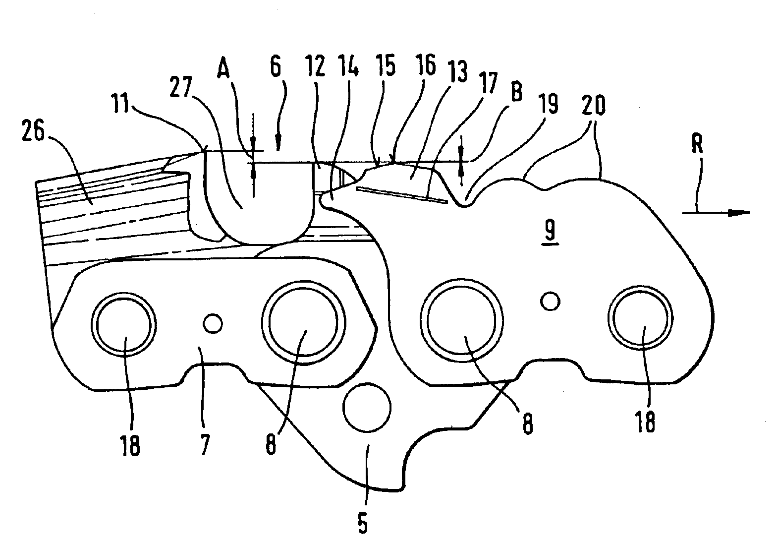
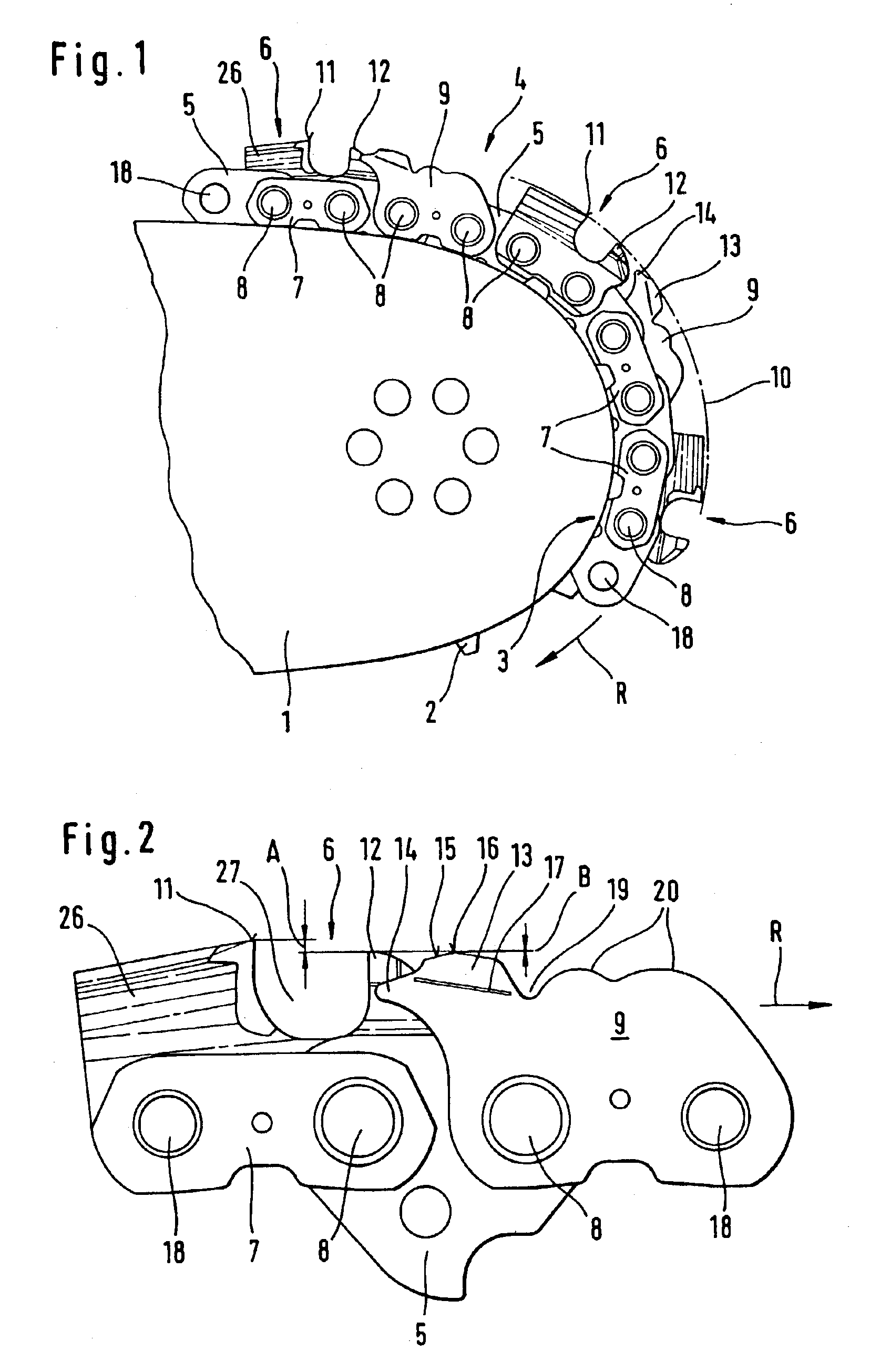
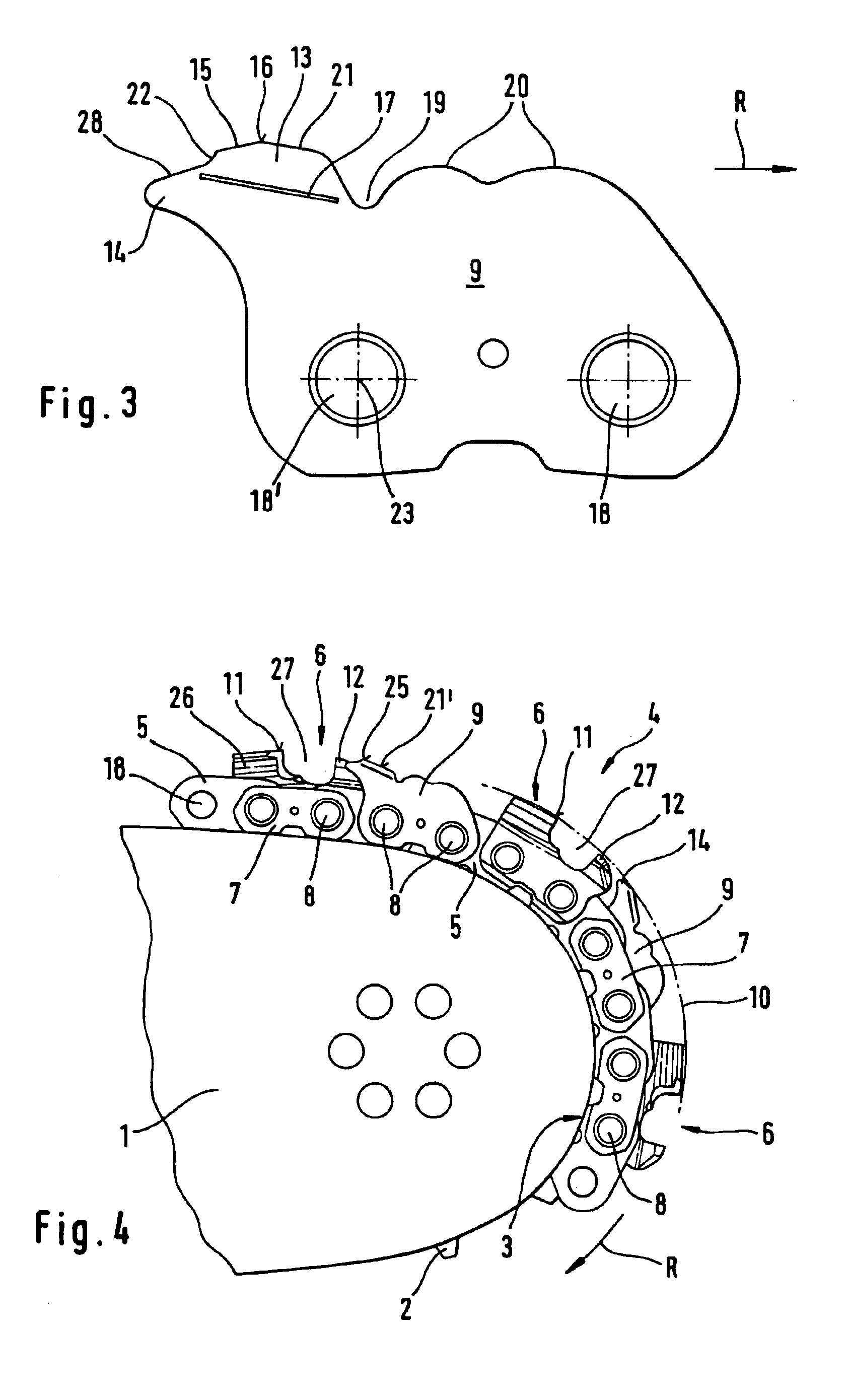
Referring now to the drawings in detail, FIG. 1 shows the front portion of a guide bar 1, which includes a guide or reversing region 3 in which is disclosed a guide star 2. Also illustrated is a portion of a saw chain 4, which is disposed upon the guide bar 1 and extends along the guide region 3. The saw chain 4 includes drive links 5 as well as cutter links 6, side or tie links 7 and safety links 9. The aforementioned links are hingedly or pivotably interconnected by means of rivets 8. Rivet receiving openings 18 can be seen on the respective first and last drive link 5 of the saw chain portion illustrated in FIG. 1.

Each of the cutter links 6 includes a cutter tooth 26 having a top cutting edge 11 and a leading depth gauge or limiter 12 as viewed in the direction of travel R. Disposed ahead of each cutter link 6, in the direction of travel R, is a safety link 9 that is provided on its outer contour with a tongue or side portion 13, and has a nose 14 directed toward the depth limite...


PUM

PropertyMeasurementUnit
Lengthaaaaaaaaaa
Depthaaaaaaaaaa

Abstract

A saw chain for a power chain saw is provided and comprises drive links and side links that connect them, whereby alternatingly disposed on one and the other longitudinal side of drive links, in place of a side link, are a cutter link and a leading safety link. The cutter link has a cutter tooth and a leading depth limiter, whereby the safety link is provided with a projecting nose for support against the base of a cut. The nose extends in the direction toward the depth limiter. The safety link is provided with a side portion disposed in front of the nose. The side portion has an elevated contact surface, which, when the saw chain is curved in the reversing region, is disposed on the path of a top cutting edge of the cutter tooth, and when the saw chain is extended reaches at least nearly to the height of the depth limiter.

Description

BACKGROUND OF THE INVENTIONThe present invention relates to a chain for a power chain saw.U.S. Pat. No. 4,562,762 discloses a saw chain for a power chain saw and comprises drive links, side links that connect them, as well as cutter links and guard links. In this connection, the cutter links and guard links are respectively alternatingly disposed on the longitudinal sides of the drive links, whereby in the direction of travel, the guard link is disposed ahead of the cutter link. The cutter link is provided on that surface thereof that faces the upper side of the chain with a curved contour that rises toward the cutter link with a nose that is formed on the end of the guard link and that when the saw chain is extended is disposed next to a depth limiter of the cutter link. In this connection, the outer end of the nose is disposed slightly below the upper point of the depth limiter, although the highest bulge of the guard link is disposed on the level of the depth limiter. In the curv...

Claims


Application Information

Patent Timeline
IPC IPC(8): B27B33/00B27B33/14
CPCB27B33/141Y10T83/909Y10T83/921Y10T83/925
Inventor MANG, HARALD
Owner ANDREAS STIHL AG & CO KG
Why Eureka
Try Eureka