Saddle for bicycle and driver supporting structure for bicycle

a technology for supporting structures and bicycles, which is applied in the direction of bicycles, bicycle equipment, mudguards, etc., can solve the problems of affecting the stability of the driver, applying undesirable high pressure to the driver's waist, and no special structure is adopted for maintaining the posture of the driver, so as to improve the stability of the bicycle, reduce the number of parts of the saddle in this configuration, and improve the posture

Inactive Publication Date: 2005-03-29
HONDA MOTOR CO LTD
View PDF9 Cites 6 Cited by
  • Summary
  • Abstract
  • Description
  • Claims
  • Application Information

AI Technical Summary

Benefits of technology

The present invention provides one of more of the following advantages over the structure of the background art. In the present invention, while the bicycle is moving, the driver can support the bicycle at the handle bar and the pedals as well as the knee grip portions. Therefore, the driver can augment the stability of the bicycle and can keep a good posture.
The number of parts of the saddle in this configuration can be reduced and the cost of the saddle can be reduced. Further, the saddle on which the knee grip portions are integrally formed can be readily produced. The knee grip portions can be removed when necessary, and the operability of the saddle is improved. Further, the knee grip portions can be mounted readily on an existing saddle, which includes only a seat face.
In addition to the stabilization of the bicycle body by the knee grip portions, splashing of mud and debris by the rear wheel can be prevented. When the driver assumes a posture wherein the hip is moved in a forward direction with respect to the bicycle body from the seat face, the hip or waist is received by th

Problems solved by technology

Further, even if the driver's waist is used for supporting the saddle, a front portion of the saddle 1 has a projection shape that appli

Method used


Image

  • Saddle for bicycle and driver supporting structure for bicycle
  • Saddle for bicycle and driver supporting structure for bicycle
  • Saddle for bicycle and driver supporting structure for bicycle

Examples


first embodiment

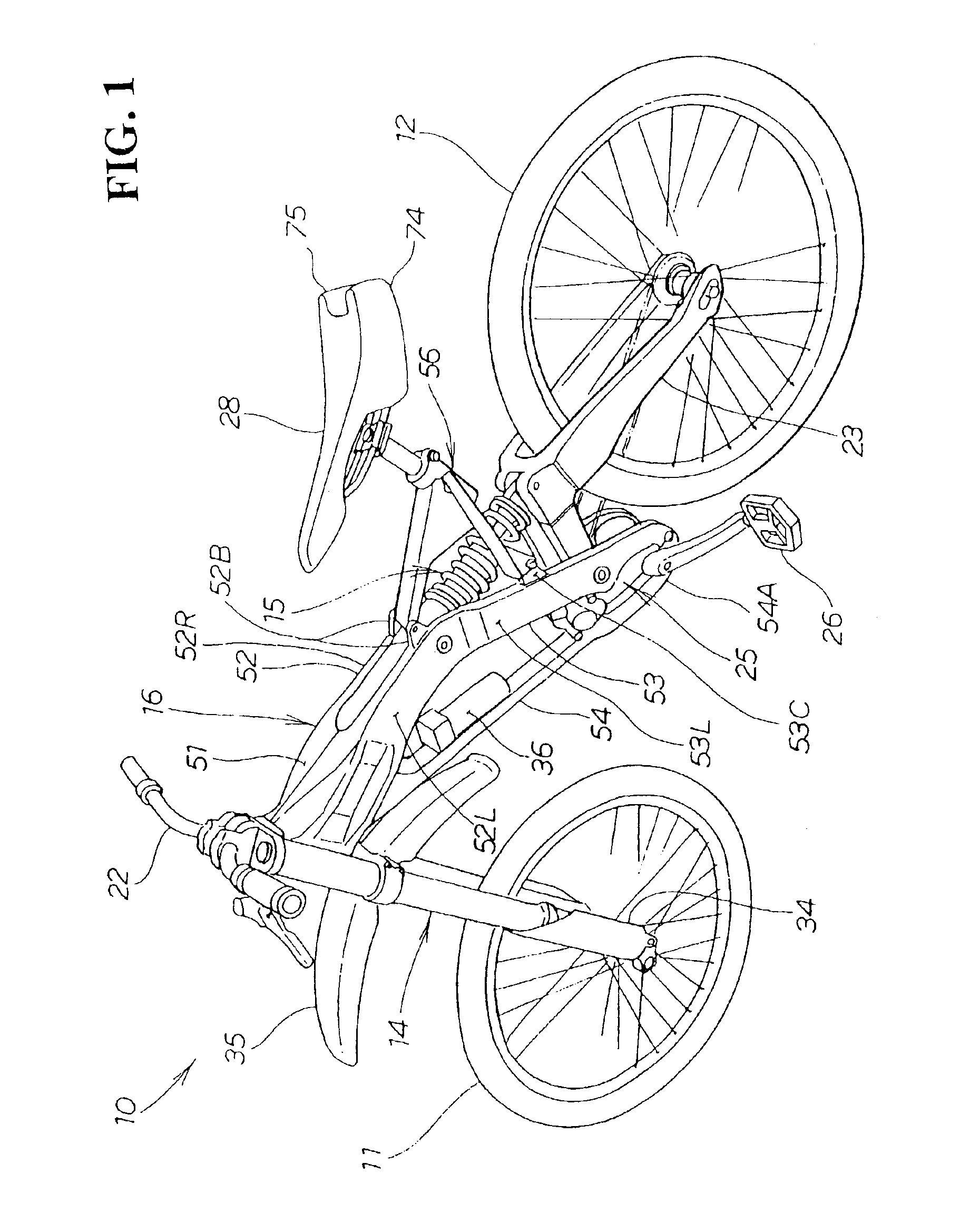
FIG. 1 is a perspective view of a bicycle including a saddle according to the present invention. The exemplary bicycle 10 is a vehicle for a downhill race. In order to use the bicycle 10 in a race wherein bicycles ride down along a unpaved, timed course in which high speed corners and jump sections are provided along a woodland path, a skiing slope, or the like, an impact from the road surface upon a front wheel 11 and a rear wheel 12 is absorbed by a front fork 14 and a rear cushion unit 15 (shock absorber) respectively. In addition, the rigidity of a body frame 16 is raised to support a high load while flexibility is provided to a portion of the body frame 16 to improve steering performance. A disk brake (hereinafter described in detail) is adopted in order to increase the braking force of the front wheel 11 and the rear wheel 12.

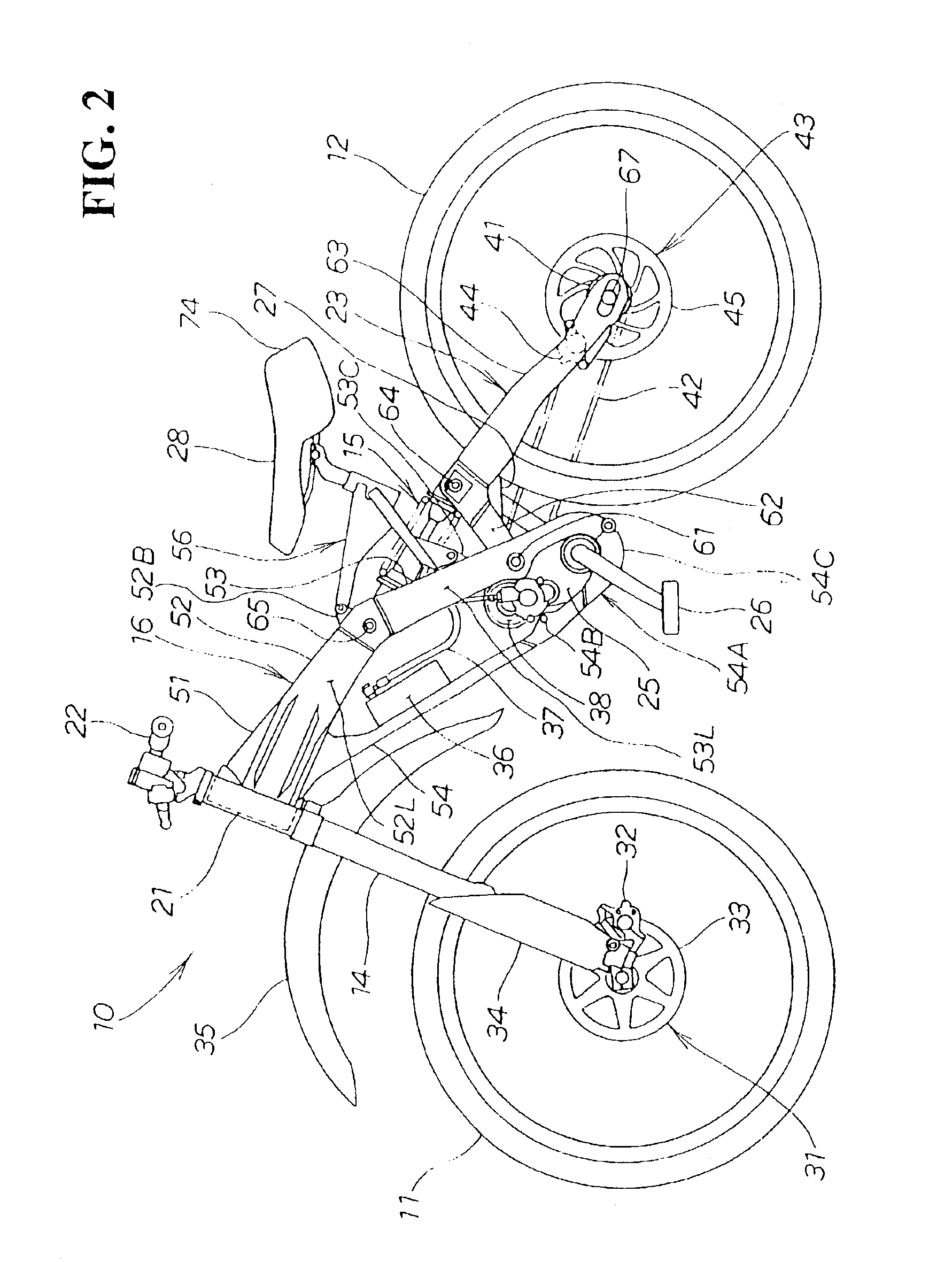
FIG. 2 is a side view of the bicycle including the saddle according to the first embodiment of the present invention. The bicycle 10 is a vehicle wherein...

second embodiment

FIG. 7 is a side view of a saddle according to the present invention. The saddle 88 wherein a knee grip portion 87 made of a resin material or a light alloy material is mounted at a rear portion and a lower portion of a saddle body 86. The form of the saddle 88 corresponds to a conventional saddle to which the knee grip portion 87 is added. It is to be noted that reference numeral 91 denotes a saddle frame that supports a bottom plate (not shown) provided on a bottom portion of the saddle body 86 and to which a saddle post 92 supported on the saddle frame 56 (refer to FIG. 2) is attached.

The knee grip portion 87 includes a pair of left and right expanded side faces 87A and 87B (the swollen side face 87B on the interior side is not shown) expanding rearward of the saddle body 86 and also expanding downward. FIG. 8 is a plan view taken along the direction indicated by an arrow mark 8 in FIG. 7 and shows that the knee grip portion 87 is disposed such that it extends from the opposite s...

third embodiment

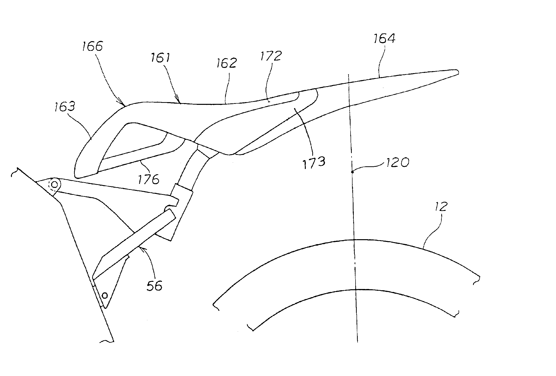
FIG. 10 is a side view of a saddle according to the present invention. The saddle 115 wherein a knee grip portion 114 made of a resin material or a light alloy material is mounted at a rear portion and a lower portion of a saddle body 86. The form of the saddle 115 corresponds to a conventional saddle to which the knee grip portion 114 is added.

The knee grip portion 114 of the saddle 115 is a panel member on which a rear extension 117 extending rearward of the vehicle body and a pair of left and right lower extensions 118, 118 (the lower extension 118 on the interior side is not shown) extending downward from the each opposite side of a front portion of the rear extension 117. The rear extension 117 is extended rearward farther than a vertical line 120, which passes the center of the axle 67 (refer to FIG. 2) of the rear wheel 12, such that it covers over the rear wheel 12 and serves as a mudguard for the rear wheel 12, e.g., as a rear fender.

As described above, the present inventio...


PUM


Abstract

The opposite side faces of a seat face of a bicycle saddle or seat on which a driver is to be seated expand rearward. The expanded, side faces also expand downward to form a pair of left and right knee grip portions such that the knee grip portions may be held between the inner sides of the knees and/or the inner parts of the thighs of the driver. While the bicycle is moving, the driver can support the bicycle at the handle bar, the pedals and the knee grip portions. Therefore, the driver can improve the stability of the bicycle and maintain a good posture. Further, if the surface area of the knee grip portions is increased, then the knee grip portions can be held readily between the inner sides of the knees and the inner parts of the thighs. Accordingly, a wide range of beneficial operating positions is provided for the aggressive use of the bicycle in applications such as mountain bike racing.

Description

CROSS-REFERENCES TO RELATED APPLICATIONSThis nonprovisional application claims priority under 35 U.S.C. § 119(a) on Patent Applications No. 2002-119413 filed in Japan on Apr. 22, 2002, and No. 2002-160826 filed in Japan on May 31, 2002, the entirety of each of which is herein incorporated by reference.BACKGROUND OF THE INVENTION1. Field of the InventionThe present invention relates to a saddle for a bicycle and a supporting structure for a driver of a bicycle, and more particularly to a saddle and supporting structure for a bicycle that augments the stability of a bicycle body.2. Description of the Background ArtSaddles for bicycles have been available in the background art, including the exemplary arrangements discussed in (1) the official gazette of Japanese Patent Laid-open No. Hei 5-147563 “Saddle for a Bicycle” and (2) the official gazette of Japanese Patent Laid-open No. Hei 8-281508 “Frame for a Bicycle.”In FIG. 3 of the document (1) discussed hereinabove, a saddle 1 whose su...

Claims


Application Information

Patent Timeline
IPC IPC(8): B62J1/00B62J25/00B62J1/28B62J15/00
CPCB62J1/00B62J25/00B62J1/28B62J25/02
Inventor MORITA, KENJIMIZUTA, KOJI
Owner HONDA MOTOR CO LTD
Why Eureka
Try Eureka