Integrating LED illumination system for machine vision systems

a technology of machine vision and illumination system, applied in the direction of instruments, lighting and heating apparatus, semiconductor devices for light sources, etc., can solve problems such as unsatisfactory systems, and achieve the effect of efficient focusing ligh

Inactive Publication Date: 2005-03-29
DATALOGIC AUTOMATION
View PDF19 Cites 255 Cited by
  • Summary
  • Abstract
  • Description
  • Claims
  • Application Information

AI Technical Summary

Benefits of technology

The present invention comprises a system for efficiently focusing light onto an illumination area. The system includes a reflector having a focusing reflective surface with a focal region, and an LED array comprising a plurality of LEDs located within the focal region. Each of the plurality of LEDs is positioned to emit light toward the focusing reflective surface. The focusing reflective surface reflects light from each of the plurality of LEDs of the LED array toward the illumination area.

Problems solved by technology

Such systems are not ideal because they are somewhat inefficient in that they consume energy at a relatively high rate and generate a large amount of heat.

Method used


Image

  • Integrating LED illumination system for machine vision systems
  • Integrating LED illumination system for machine vision systems
  • Integrating LED illumination system for machine vision systems

Examples


Embodiment Construction

)

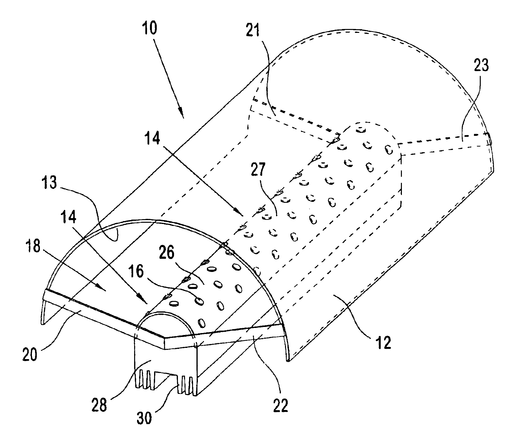
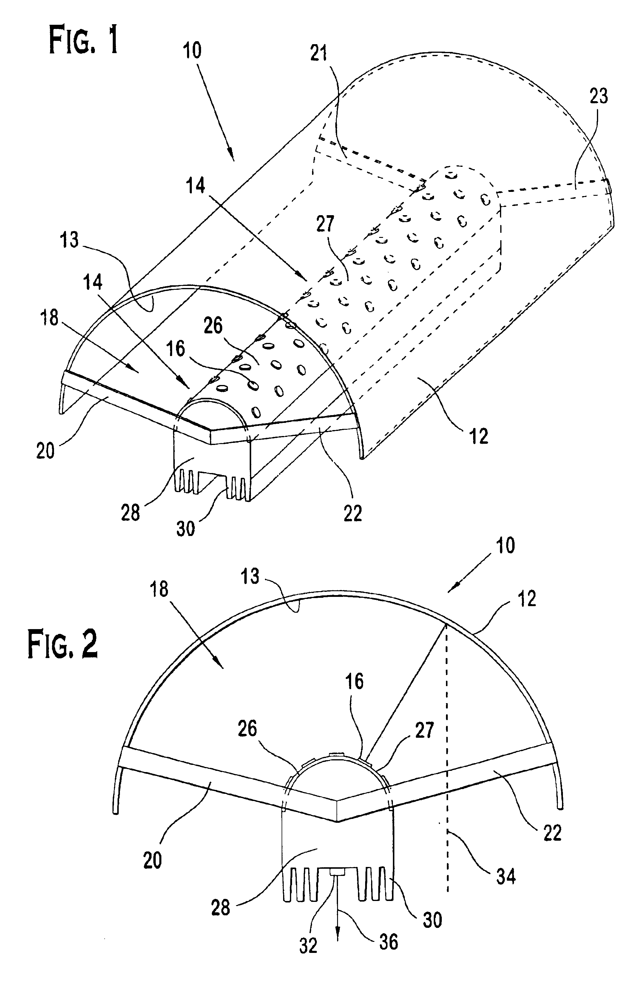
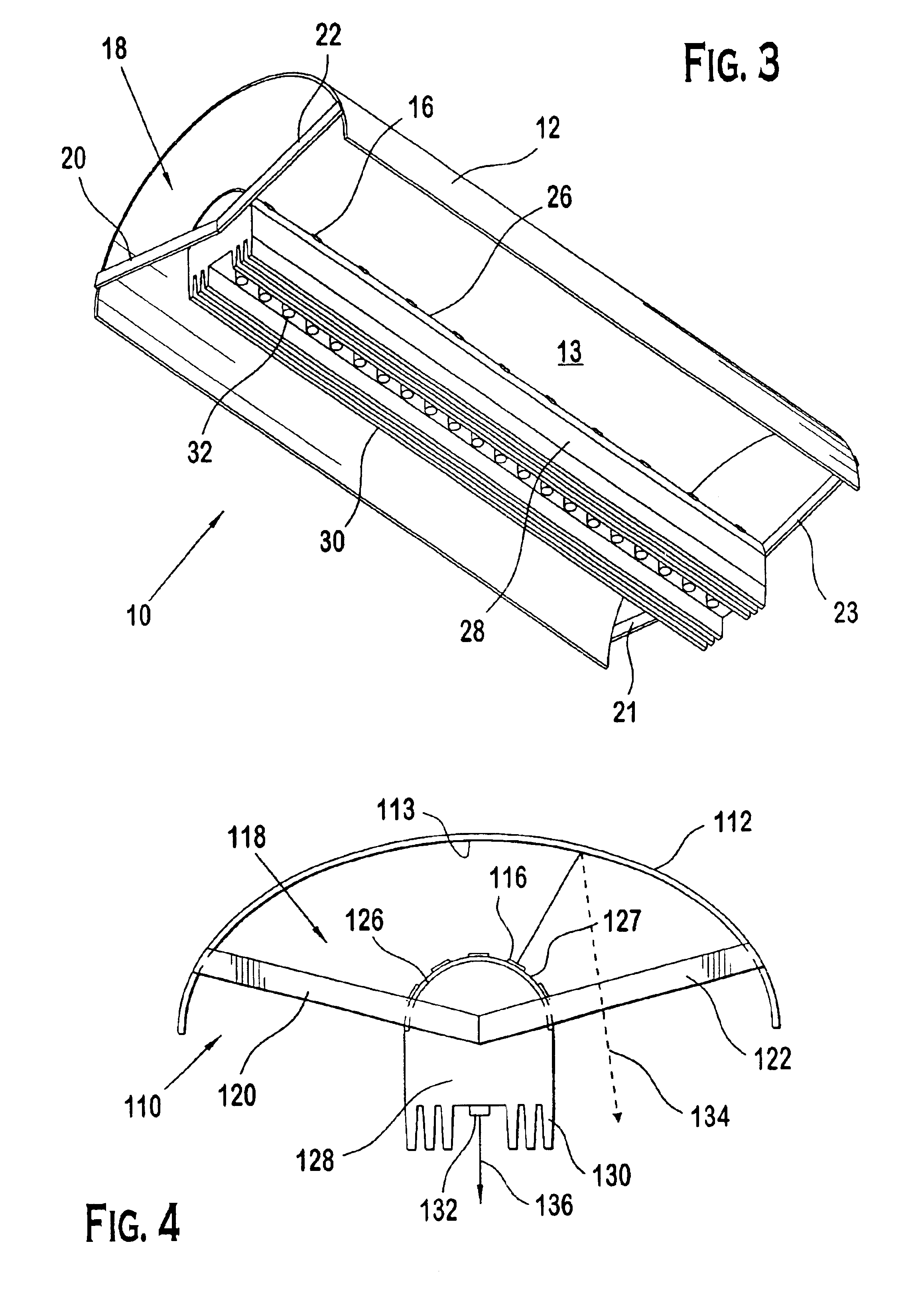
Referring now to FIGS. 1-3, reference numeral 10 refers generally to an illumination system in accordance with the present invention. The system 10 comprises a reflector 12 and an LED array 14 and is best suited for linear scanning systems because it generates a slender, elongated illumination area.

The reflector 12 includes a focusing reflective surface 13 that is concave in shape. An elliptical cross-sectional shape is preferred, but other shapes, such as parabolic and hyperbolic could be used, for example. The reflector 12 can be formed of any suitable reflective material. The preferred shape of the reflective surface 13 would vary depending upon the application in which the system 10 is being used. Factors determining the preferred shape include the desired light beam thickness and operating range, for example.

The LED array 14 comprises a plurality of surface mounted LEDs 16 that are arranged to emit light energy (shown schematically as line 34) toward the reflective surface 13....


PUM

PropertyMeasurementUnit
illumination areaaaaaaaaaaa
flexibleaaaaaaaaaa
areaaaaaaaaaaa

Abstract

A system for focusing light on an illumination area. The system includes a reflector having a focusing reflective surface and a focal region and an LED array having a plurality of LEDs located within the focal region. Each of the plurality of LEDs in the LED array is positioned to emit light toward the focusing reflective surface. The focusing reflective surface reflects light from each of the plurality of LEDs of the LED array toward the illumination area.

Description

BACKGROUNDThe present invention relates to an illumination system for use with machine vision systems, such as optical and barcode scanning systems. More particularly, it relates to a system for focusing light on a line or area in which a machine vision system collects image data.In order to increase accuracy and maintain consistency in the data collected by machine vision systems it is important to have a direct source of light to fully illuminate the area being scanned (hereinafter the “illumination area”). In the case of a linear scanner, a narrow illumination line is sufficient. For area-array based scanning equipment such as video cameras, it is necessary to illuminate a wider area. As used in this application and the appended claims, the term “illumination area” should be understood as including both area and line illumination. Such illumination systems have traditionally consisted of either direct illumination or a combination of direct and reflected illumination, in which li...

Claims


Application Information

Patent Timeline
Patent Type & Authority Patents(United States)
IPC IPC(8): G01N21/88
CPCF21V29/76G01N21/8806F21V7/0008F21V7/005F21V19/001F21V29/004F21Y2111/004F21Y2111/005F21Y2101/02F21V29/74F21Y2115/10F21Y2107/20F21Y2107/30
Inventor HECHT, KURT
Owner DATALOGIC AUTOMATION
Why Eureka
Try Eureka