Baseball or softball bat, bat base member and elastic sleeve

a elastic sleeve technology, applied in the field of baseball or softball bat rebound property improvement, can solve the problems of large bat mass and difficult design, and achieve the effect of good durability

Inactive Publication Date: 2005-03-29
MIZUNO CORPORATION
View PDF21 Cites 64 Cited by
  • Summary
  • Abstract
  • Description
  • Claims
  • Application Information

AI Technical Summary

Benefits of technology

An object of the present invention is to provide a bat having good durability and capable of

Problems solved by technology

If the bat is entirely coated with the elastic body, the mass of the bat will be larger,

Method used


Image

  • Baseball or softball bat, bat base member and elastic sleeve
  • Baseball or softball bat, bat base member and elastic sleeve
  • Baseball or softball bat, bat base member and elastic sleeve

Examples


first embodiment

(First Embodiment)

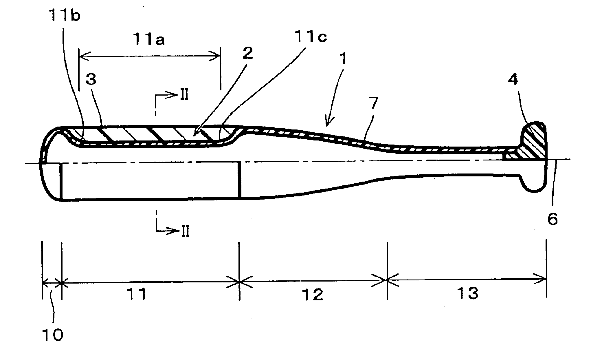
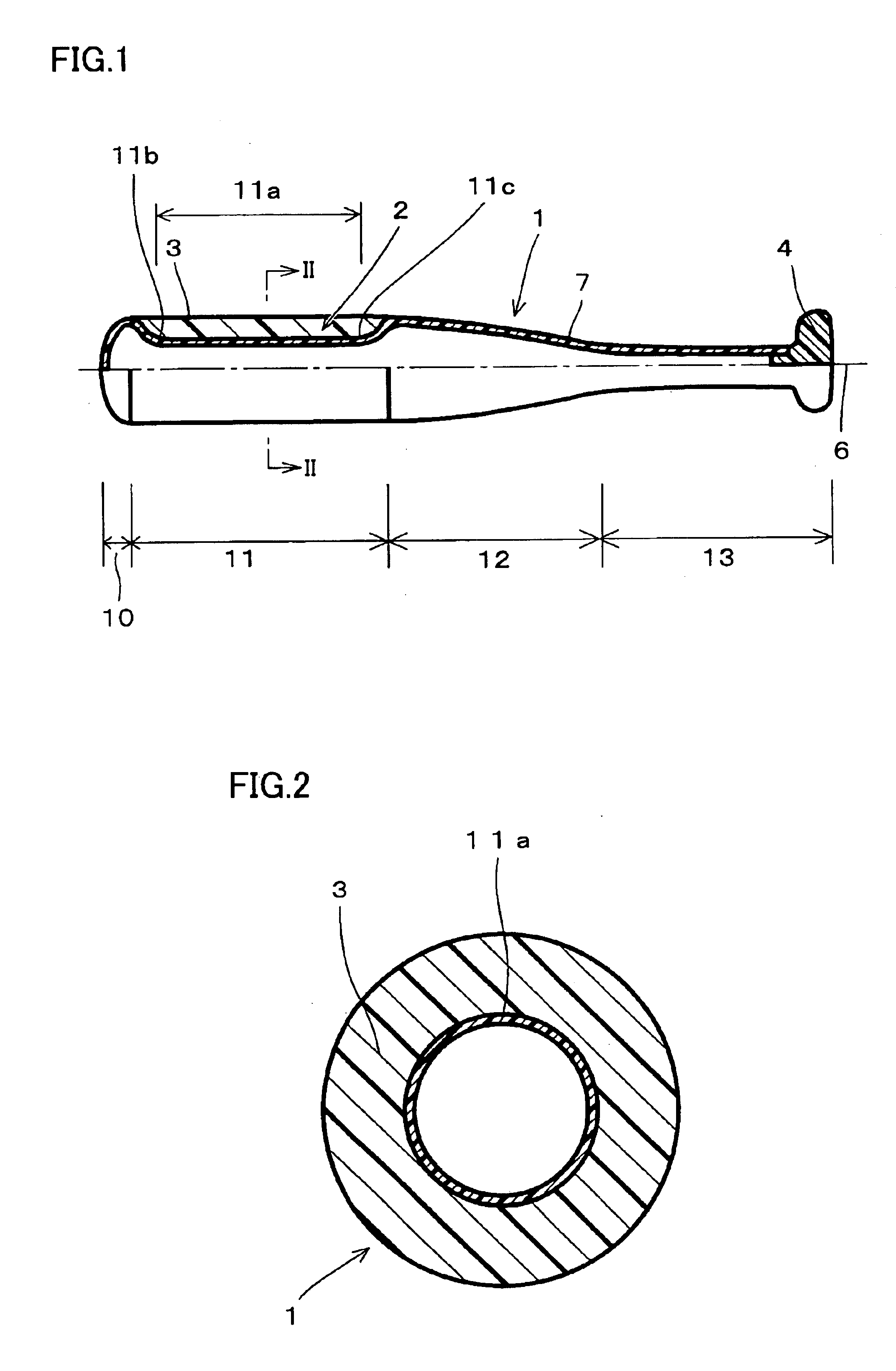
Referring to FIGS. 1 and 2, a first embodiment of a bat according to the present invention will be described.

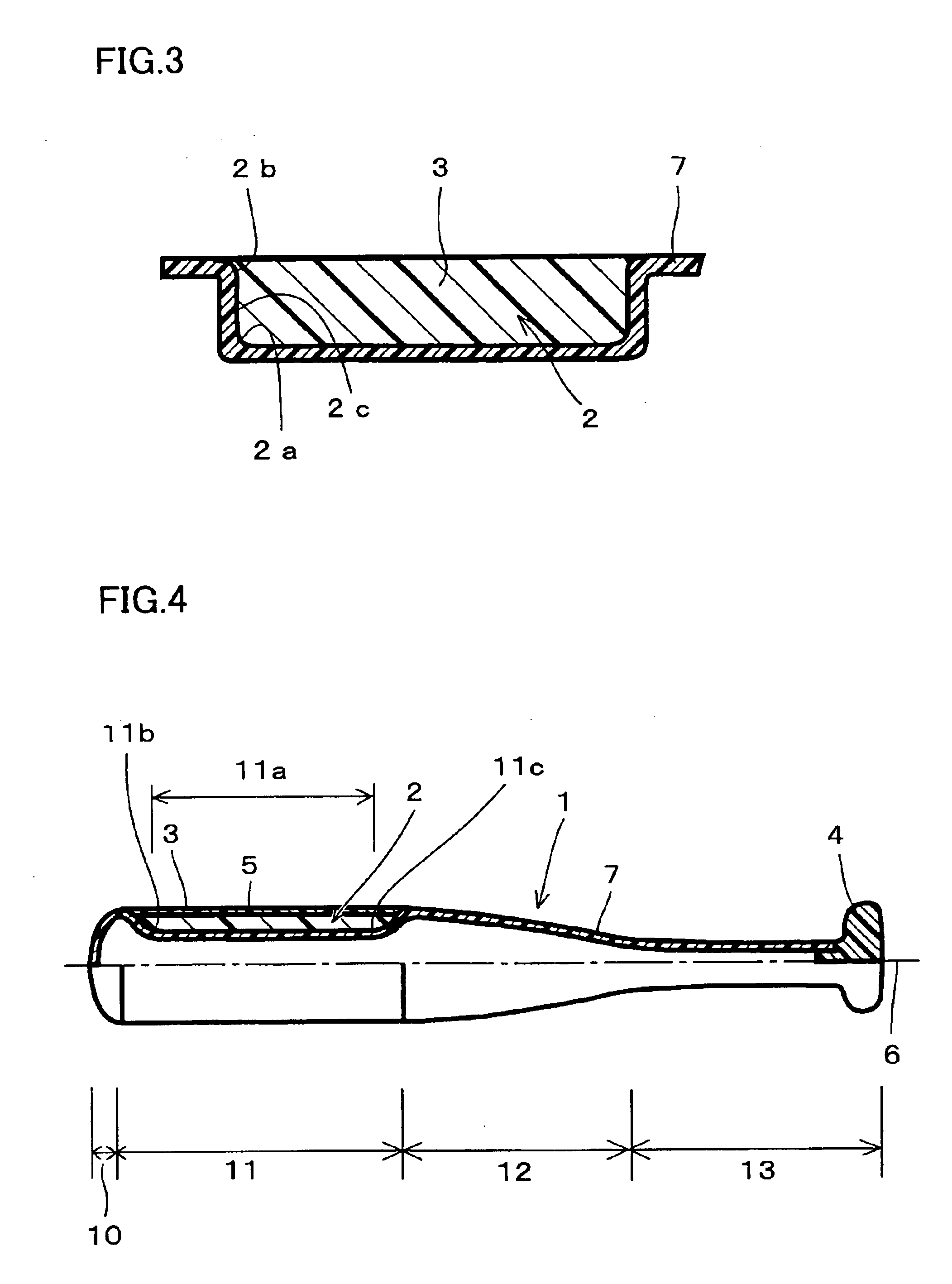
A bat according to the present invention has a depression of a ball-hitting portion integrally coated with an elastic body that has a largest rebound property confirmed in various experiments. As shown in FIGS. 1 and 2, a baseball or softball bat 1 includes a tip portion 10, a ball-hitting portion 11, a tapered portion 12 and a grip portion 13. A bat base member 7 constituting bat 1 is provided with a depression 2 in a portion to be ball-hitting portion 11. Desirably, the depression is formed with a ball-hitting center portion 11a having an outer diameter smaller than that of ball-hitting portion 11, and an outer diameter thereof from an end 11b of a tip portion side of ball-hitting center portion 11a to the boundary of tip portion 10 and an outer diameter from an end 11c of a tapered portion side of ball-hitting center portion 11a to the boundary of tapered...

second embodiment

(Second Embodiment)

Referring to FIGS. 5 to 7, a second embodiment of a bat according to the present invention will be described.

As shown in FIGS. 5 to 7, bat 1 basically has the same structure as the one shown in FIG. 4 except for the shape of depression 2. In other words, depression 2 may include a center portion bottom wall 8 as a small outer diameter portion of ball hitting center portion 11a, distance of which from central axis 6 of baseball or softball bat 1 is smaller than distance R1 (see FIG. 7) from central axis 6 to an outermost circumferential portion of ball-hitting portion 11; an end portion region 15 as a stepped portion bottom wall (see FIG. 5), distance of which from central axis 6 is larger than distance R2 (see FIG. 7) from central axis 6 to center portion bottom wall 8 of ball-hitting center portion 11a and is smaller than distance R1 from central axis 6 to outermost circumferential portion 9 of ball-hitting portion 11, and positioned at both ends of ball-hitting ...

example 1

In order to verify the effect of the bat according to the present invention shown in FIGS. 1 and 2, an actual hitting test was conducted.

A rubber-baseball bat 1 used in the test as an example of the bat according to the present invention shown in FIGS. 1 and 2, was hollow and made of fiber-reinforced plastic. In the bat, a tip portion 10, a ball-hitting portion 11 having a depression 2, a tapered portion 12 and an outer shell of a grip portion 13 (a bat base member 7) were formed with internal pressure molding. A grip end 4 separately formed with a synthetic resin was inserted and adhered to the end of grip portion 13. After sandblasting depression 2 of ball-hitting portion 11, the bat was cast molded, using a mold designed to integrally coat depression 2 with elastic body 3. Here, for elastic body 3, a polyurethane foam having JIS C hardness of 43, specific gravity of 0.35 and elasticity modulus (tensile stress in 300% elongation) of 1.23 MPa was used.

Outer diameter of ball-hitting...


PUM


Abstract

A ball-hitting portion is integrally coated with an elastic body, and thus a bat with durability that can carry the ball far can be obtained. The baseball or softball bat includes a tip portion, a ball-hitting portion, a tapered portion and a grip portion. A depression in the ball-hitting portion is integrally coated with the elastic body having a high rebound property value as a physical property. Thus, when hitting the ball, the elastic body will be compressed and deform, and energy loss due to the ball deformation will be suppressed. Moreover, the ball is carried additionally with a restoring force of the elastic body. Consequently, the bat has rebound property superior to a conventional one, and can carry the ball farther.

Description

CROSS-REFERENCE TO RELATED APPLICATIONS AND CLAIM OF PRIORITYThis application claims priority from Japanese Patent Application No. 2001-135294, filed 2 May 2001 and Japanese Patent Application No. 2002-101547 filed 3 Apr. 2002.BACKGROUND OF THE INVENTION1. Field of the InventionThe present invention relates to improvements in rebound property of a baseball or softball bat.2. Description of the Background ArtBaseball or softball bats (hereinafter, referred to as a “bat”) made of various materials are commercially available. Some are made of wood or metal such as titanium, titanium alloy, aluminum alloy or the like. Others are made of fiber-reinforced plastic in which a matrix resin is impregnated and cured in carbon fiber, glass fiber or the like.When a bat is structured with only one of those materials, however, it is difficult to change a property value of the bat to a large extent. Therefore, a bat made from a combination of various materials has been developed.In order to achieve...

Claims


Application Information

Patent Timeline
IPC IPC(8): A63B59/06A63B59/00A63B59/50A63B59/54A63B59/58A63B60/54A63B102/18
CPCA63B59/0092A63B59/06A63B2059/0007A63B59/50A63B59/51A63B59/52A63B59/54A63B59/58A63B60/54A63B2102/18A63B2102/182A63B60/004
Inventor OGAWA, MASAOISHIDA, KAZUYAKIDA, TOSHIAKI
Owner MIZUNO CORPORATION
Why Eureka
Try Eureka