Circumferential ablation device assembly

a circumferential ablation and device technology, applied in the field of surgical devices, can solve the problems of cardiac arrhythmias, general belief that they are entirely effective, and abnormal wall conditions, and achieve the effect of preventing atrial arrhythmias and high-invasive methods

Inactive Publication Date: 2005-03-29
RGT UNIV OF CALIFORNIA
View PDF313 Cites 143 Cited by
  • Summary
  • Abstract
  • Description
  • Claims
  • Application Information

AI Technical Summary

Problems solved by technology

Diseased or structurally damaged blood vessels may bring about various abnormal wall conditions.
Cardiac arrhythmias, and atrial fibrillation in particular, persist as common and dangerous medical ailments, especially in the aging population.
However, such pharmacological solutions are not generally believed to be entirely effective in many cases, and may in some cases result in proarrhythmia and long term inefficacy.
However, more recent reports predict that the surgical “maze” procedure may be substantially efficacious when performed only in the left atrium, such as is disclosed in Sueda et al., “Simple Left Atrial Procedure for Chronic Atrial Fibrillation Associated With Mitral Valve Disease” (1996).
While the “maze” procedure as reported by Cox and others, and also other surgical procedures, have met some success in treating patients with atrial arrhythmia, its highly invasive methodology is believed to be prohibitive in most cases.

Method used


Image

  • Circumferential ablation device assembly
  • Circumferential ablation device assembly
  • Circumferential ablation device assembly

Examples


Embodiment Construction

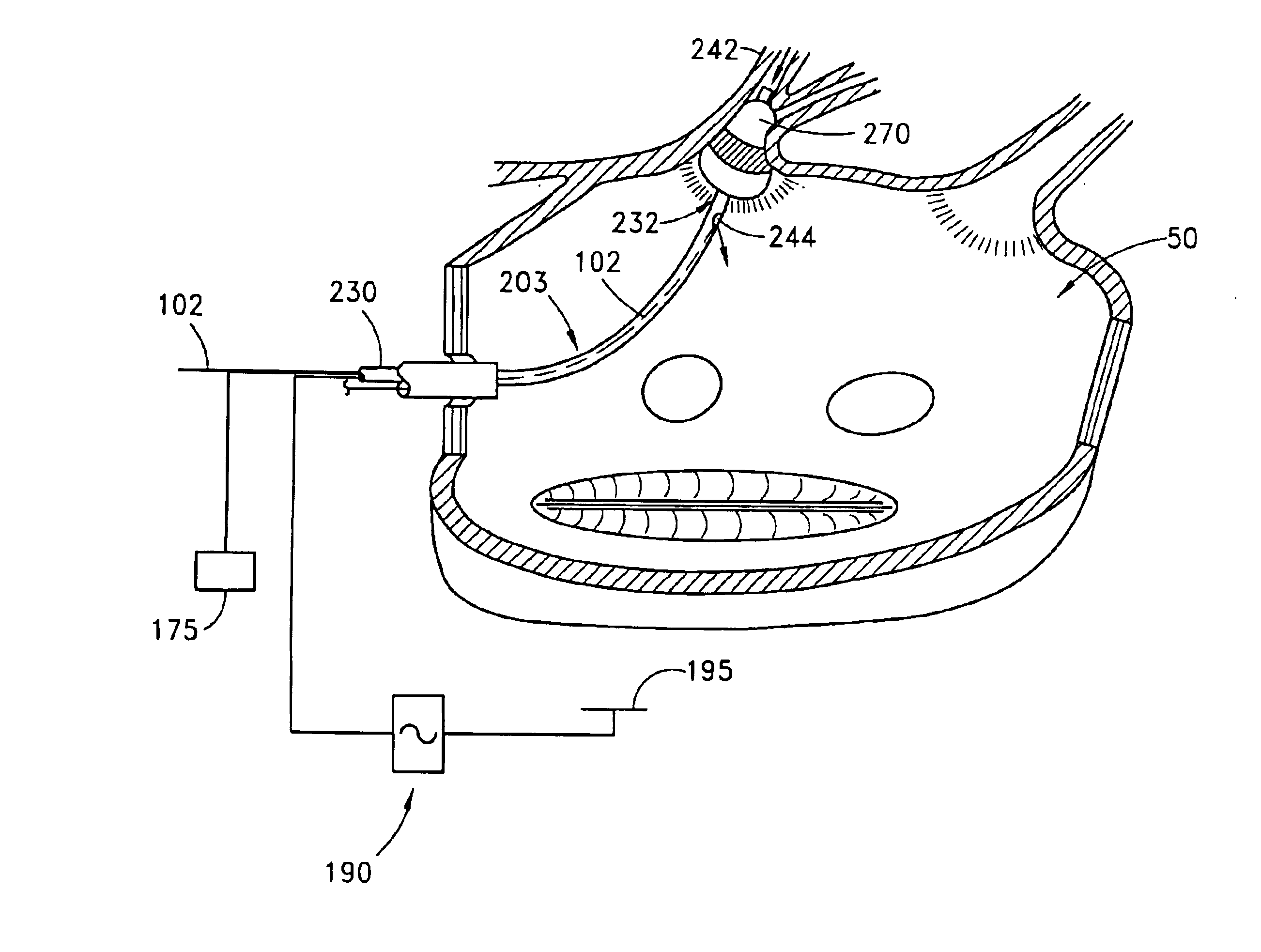
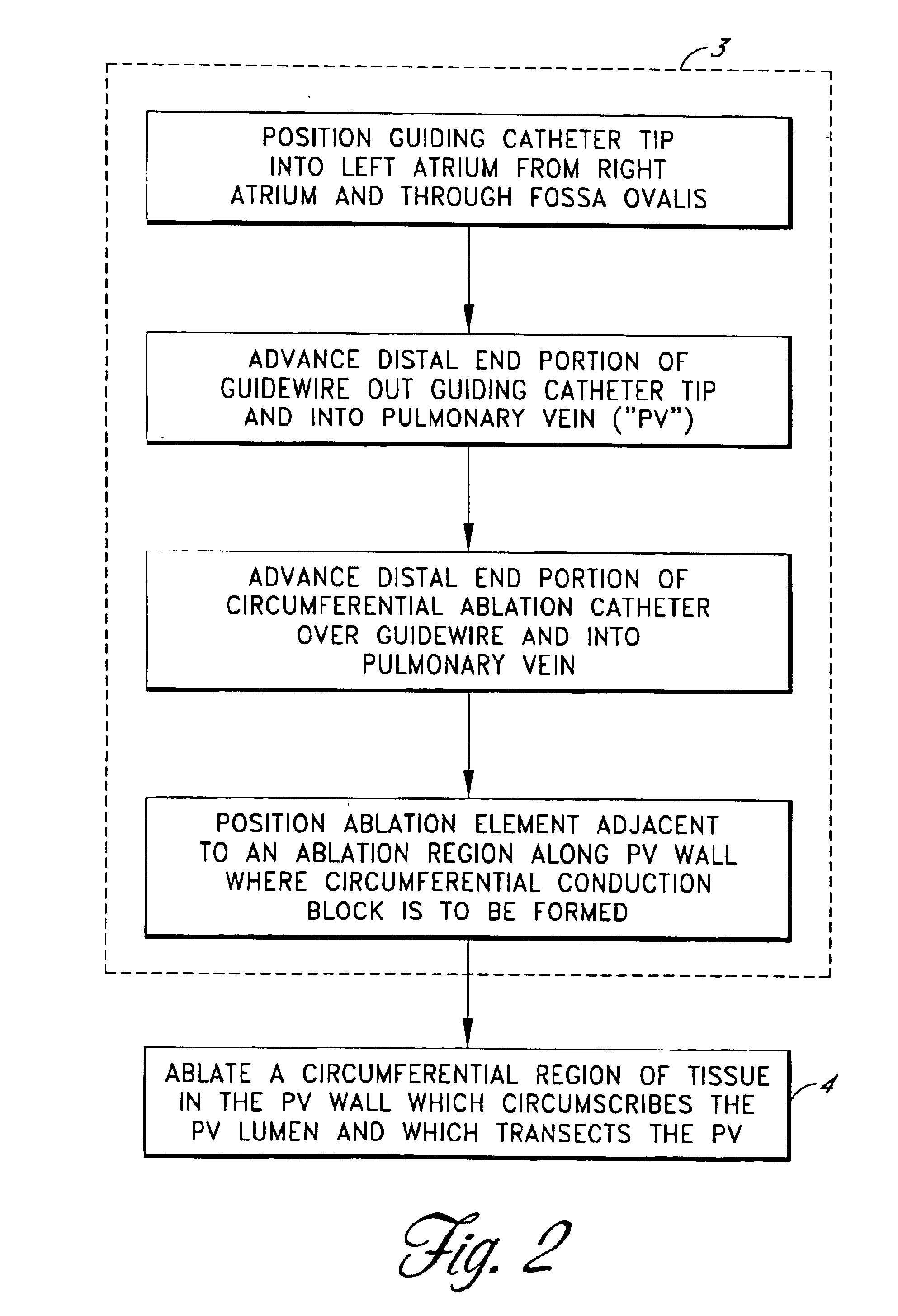
As will be described with reference to the detailed embodiments below, the present invention is a circumferential ablation device assembly which is adapted to treat patients with atrial arrhythmia by forming a circumferential conduction block in a pulmonary vein which blocks electrical conduction along the longitudinal axis of the pulmonary vein wall and into the left atrium.

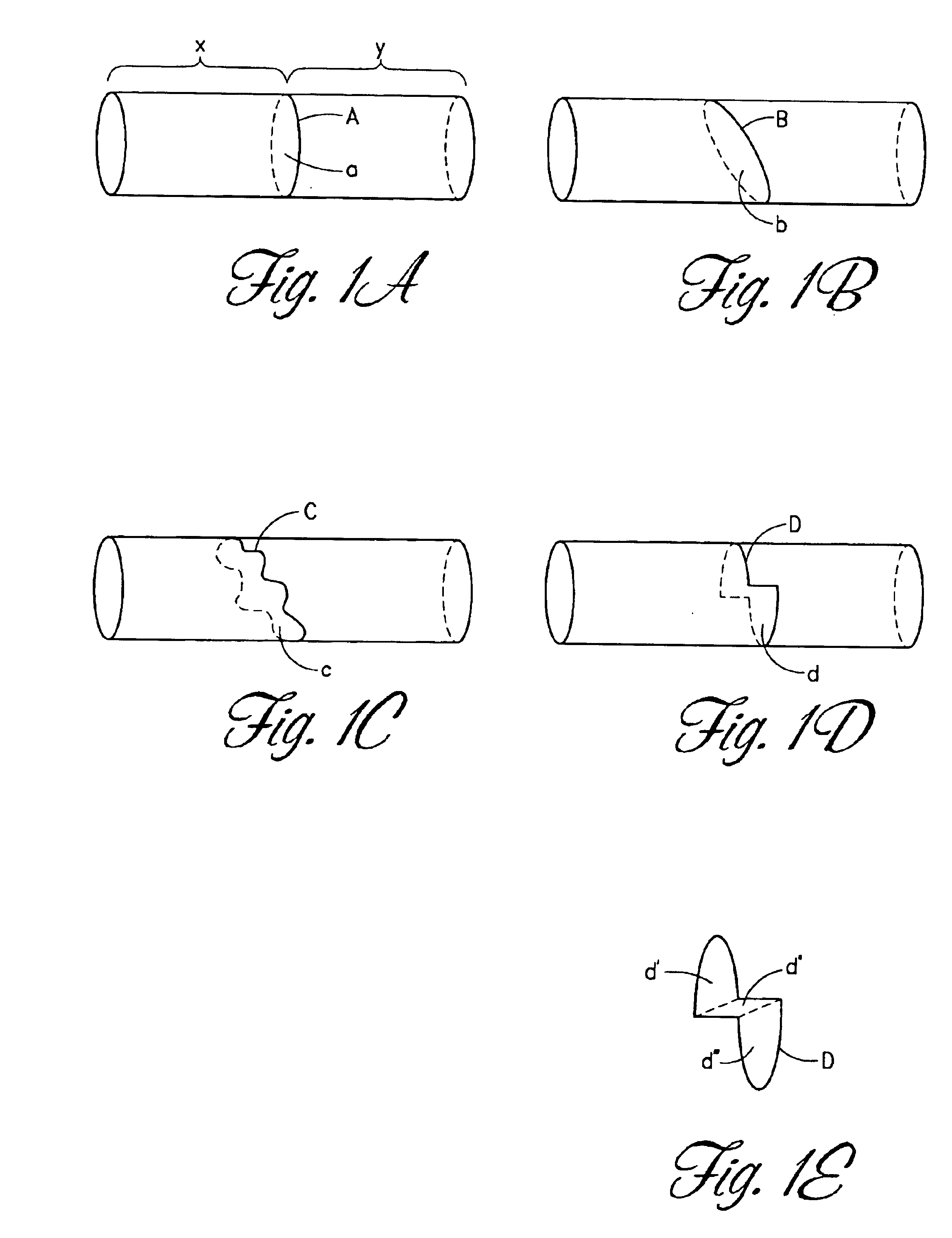
The terms “circumference” or “circumferential”, including derivatives thereof, are herein intended to mean a continuous path or line which forms an outer border or perimeter that surrounds and thereby defines an enclosed region of space. Such a continuous path starts at one location along the outer border or perimeter, and translates along the outer border or perimeter until it is completed at the original starting location to enclose the defined region of space. The related term “circumscribe,” including derivatives thereof, is herein intended to mean to enclose, surround, or encompass a defined region of space...


PUM


Abstract

This invention is a circumferential ablation device assembly which is adapted to forming a circumferential conduction block in a pulmonary vein. The assembly includes a circumferential ablation element which is adapted to ablate a circumferential region of tissue along a pulmonary vein wall which circumscribes the pulmonary vein lumen, thereby transecting the electrical conductivity of the pulmonary vein against conduction along its longitudinal axis and into the left atrium. The circumferential ablation element includes an expandable member with a working length that is adjustable from a radially collapsed position to a radially expanded position. An equatorial band circumscribes the outer surface of the working length and is adapted to ablate tissue adjacent thereto when actuated by an ablation actuator. The equatorial band has a length relative to the longitudinal axis of the expandable member that is narrow relative to the working length, and is also substantially shorter than its circumference when the working length is in the radially expanded position. A pattern of insulators may be included over an ablation element which otherwise spans the working length in order to form the equatorial band described. The expandable member is also adapted to conform to the pulmonary vein in the region of its ostium, such as by providing a great deal of radial compliance or by providing a taper along the working length which has a distally reducing outer diameter. A linear ablation element is provided adjacent to the circumferential ablation element in a combination assembly which is adapted for use in a less-invasive “maze”-type procedure in the region of the pulmonary vein ostia in the left ventricle.

Description

TECHNICAL FIELDThe present invention is a surgical device. More specifically, it is a circumferential ablation device assembly which is adapted to ablate a selected circumferential region of tissue along a pulmonary vein wall and thereby form a circumferential conduction block against conduction along the longitudinal axis of the pulmonary vein wall.BACKGROUNDMany abnormal medical conditions in humans and other mammals have been associated with disease and other aberrations along the lining or walls which define several different body spaces. In order to treat such abnormal wall conditions of the body spaces, medical device technologies adapted for delivering specific forms of ablative energy to specific regions of targeted wall tissue from within the associated body space have been developed and disclosed.The terms “body space,” including derivatives thereof, is herein intended to mean any cavity or lumen within the body which is defined at least in part by a tissue wall. For examp...

Claims


Application Information

Patent Timeline
Patent Type & Authority Patents(United States)
IPC IPC(8): A61B18/00A61N7/02A61N7/00A61B17/00A61B17/22A61B18/14
CPCA61B18/00A61N7/02A61B18/1492A61B18/1815A61B2017/00243A61B2017/22038A61B2017/22054A61B2017/22067A61B2018/00011A61B2018/0016A61B2018/00214A61B2018/00273A61B2018/00285A61B2018/00291A61B2018/00369A61B2018/00375A61B2018/00797A61B2018/00815A61B2018/00821A61B2018/00839A61B2018/00898A61B2018/00994A61B2218/002
Inventor LESH, MICHAEL D.ROSS, MICHAEL RONALDLANGBERG, JONATHAN J.PEACOCK, III, JAMES C.
Owner RGT UNIV OF CALIFORNIA
Why Eureka
Try Eureka