Focalized stent implantation

a balloon dilatation catheter and stent technology, applied in the field of catheters, can solve the problems of insufficient relief of stenosis, damage to the native vessel adjacent to the obstruction, balloon to inflate around the plaque,

Inactive Publication Date: 2005-03-29
RADIANCE MEDICAL SYST
View PDF48 Cites 74 Cited by
  • Summary
  • Abstract
  • Description
  • Claims
  • Application Information

AI Technical Summary

Benefits of technology

There is provided in accordance with one aspect of the present invention a balloon catheter comprising an elongate flexible tubular body and an inflatable balloon on the tubular body. A proximal segment, a central segment and a distal segment on the balloon are inflatable to a first inflated diameter at a first inflation pressure, and the proximal and distal segment expand to a second, greater inflated diameter at a second greater inflation pressure. The central segment of the balloon remains at a diameter which is less than the second diameter, at the second inflation pressure. In one embodiment, the balloon additionally comprises at least one expansion limiting band on the central segment to limit inflation of the central segment of the balloon. Preferably, the expansion limiting band limits expansion of the central segment to no more than about the first inflated diameter.

Problems solved by technology

One difficulty with compliant balloons, however, is that inflation within a difficult lesion can cause the balloon to inflate around the plaque to produce a generally hourglass-shaped inflated profile.
This can result in damage to the native vessel adjacent the obstruction, while at the same time failing to sufficiently alleviate the stenosis.
However, the clinician has no effective way to assess the actual inflated diameter of the balloon in vivo based upon the unconstrained in vitro balloon specifications.
In applications where a relatively accurate inflated diameter is desired, such as in certain dilatations or in the implantation of tubular stents, the clinician using prior dilatation balloons thus may not have enough information about the dilatation characteristics of a particular lesion to optimize the dilatation or stent implantation procedure.

Method used


Image

  • Focalized stent implantation
  • Focalized stent implantation
  • Focalized stent implantation

Examples


Embodiment Construction

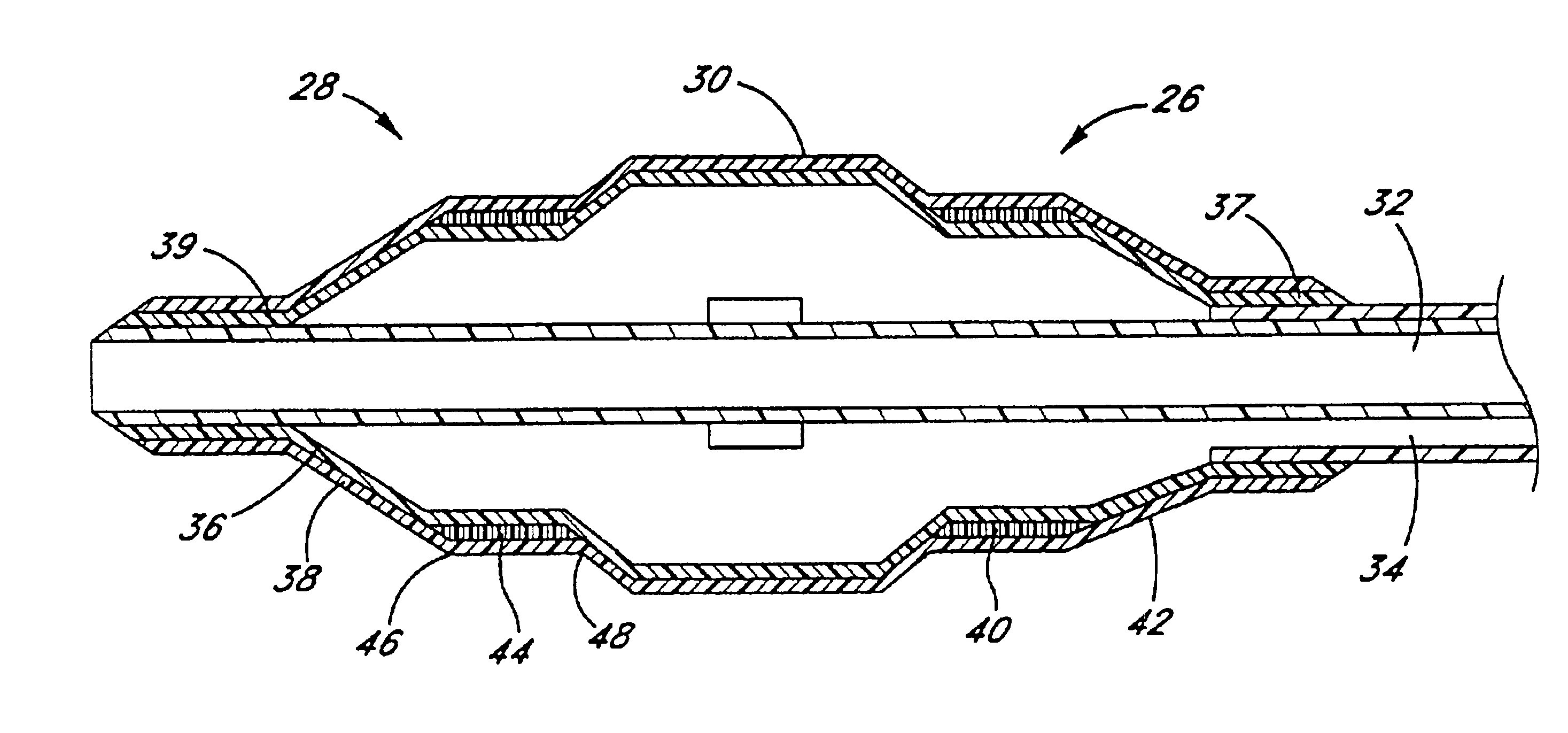
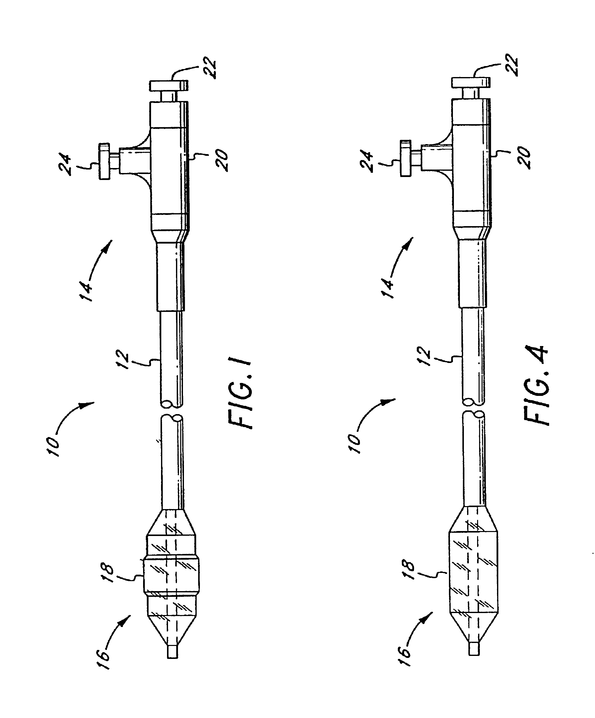
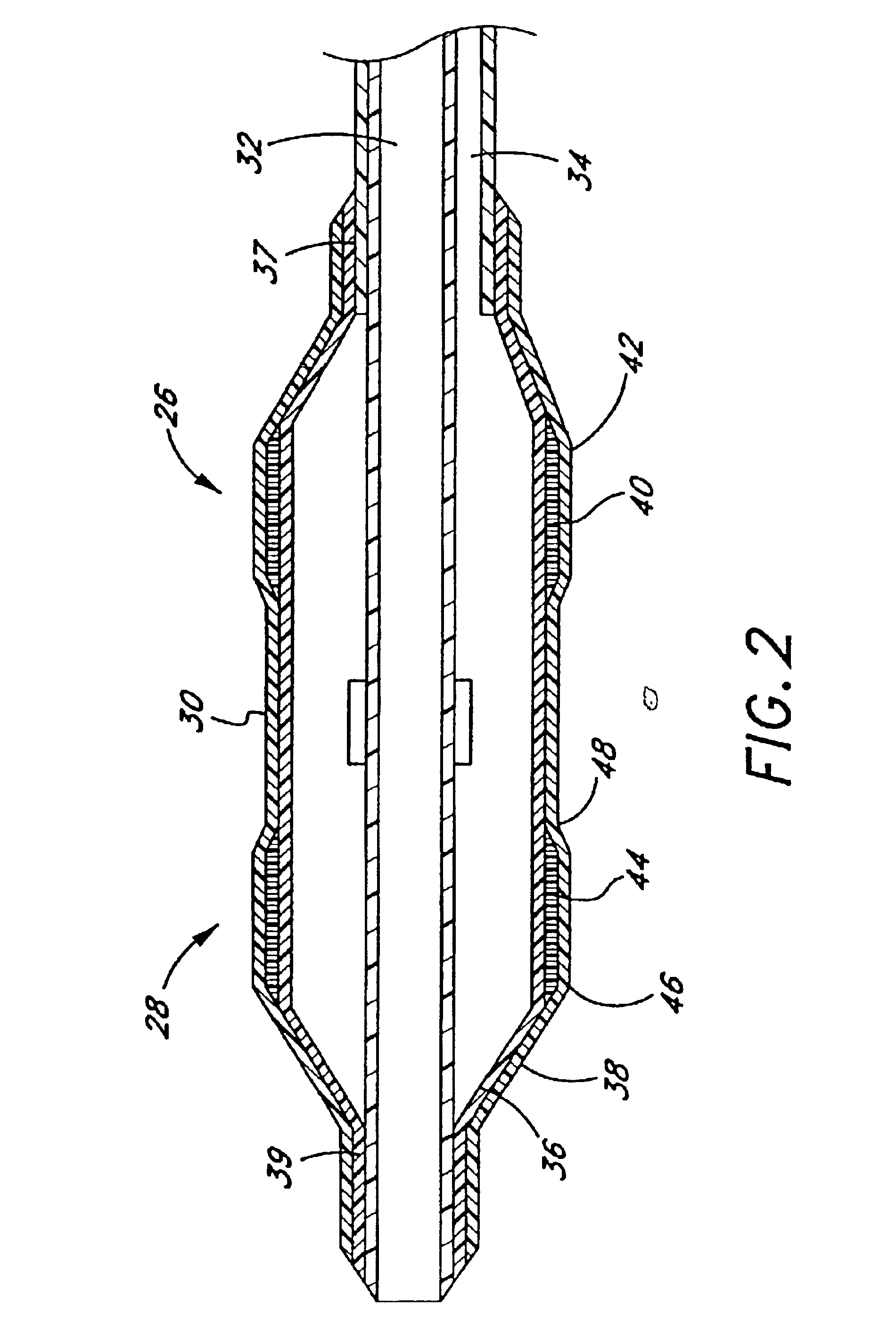
Referring to FIG. 1, there is disclosed a variable diameter inflation catheter 10 in accordance with of one aspect of the present invention. Catheters embodying additional features known in the vascular dilatation art, such as implantable stents, drug delivery, perfusion and dilatation features, or any combination of these features, can be used in combination with the focal balloon of the present invention as will be readily apparent to one of skill in the art in view of the disclosure herein.

The catheter 10 generally comprises an elongate tubular body 12 extending between a proximal control end 14 and a distal functional end 16. The length of the tubular body 12 depends upon the desired application. For example, lengths in the area of about 120 cm to about 140 cm are typical for use in percutaneous transluminal coronary angioplasty applications.

The tubular body 12 may be produced in accordance with any of a variety of known techniques for manufacturing balloon-tipped catheter bodie...


PUM


Abstract

Disclosed is a focal balloon having at least one reference zone and a focal zone. In one embodiment, the reference zone and focal zone are inflatable to a first generally cylindrical profile at a first pressure. At a second, greater pressure, the focal section expands to a second, greater diameter, while the reference zone remains substantially at the first diameter. In an alternate embodiment, the focal zone and the reference zone are inflatable to their respective predetermined diameters at the inflation pressure, in the absence of constricting lesions or anatomical structures. Multiple lobed and drug delivery embodiments are also disclosed.

Description

BACKGROUND OF THE INVENTIONThe present invention relates to catheters for insertion into a body lumen. More particularly, the present invention relates to “focal” balloon dilatation catheters for use in the vascular system. As used herein, “focal” balloons are balloons which focus or concentrate expansive energy at one or more predetermined regions along the surface of the balloon.Prior art vascular dilatation balloons on typical dilatation catheters tend to fall into one of two broad classes. Most are considered noncompliant balloons, formed from a generally nondistensible material such as polyethylene. The perceived advantage of the noncompliant balloons is that they exhibit a substantially uniform exterior inflated profile which remains substantially unchanged upon incremental increases in inflation pressure. In theory, noncompliant balloons are advantageous because they allow the introduction of increased inflation pressure to break particularly calcified lesions, yet retain a p...

Claims


Application Information

Patent Timeline
Patent Type & Authority Patents(United States)
IPC IPC(8): A61M25/10A61M25/00A61M29/02A61F2/86A61M29/00
CPCA61F2/86A61M25/1002A61M25/1027A61M25/104A61M25/1029A61M25/10A61M25/1018A61M2025/1084A61M25/1034A61M2025/1059A61M2025/1072A61M2025/1075A61F2/958A61M25/10184
Inventor CROCKER, MICHAELSHIMADA, LYNN M.
Owner RADIANCE MEDICAL SYST
Why Eureka
Try Eureka