
Mast lighting system

a technology for outdoor lighting and masts, which is applied in fixed installations, lighting and heating equipment, and ways, etc., can solve problems such as failure, interruption of service throughout the grid, and impaired performance of such a system

Inactive Publication Date: 2005-03-29
GINSBURG THOMAS A
View PDF70 Cites 43 Cited by
  • Summary
  • Abstract
  • Description
  • Claims
  • Application Information

AI Technical Summary

Benefits of technology

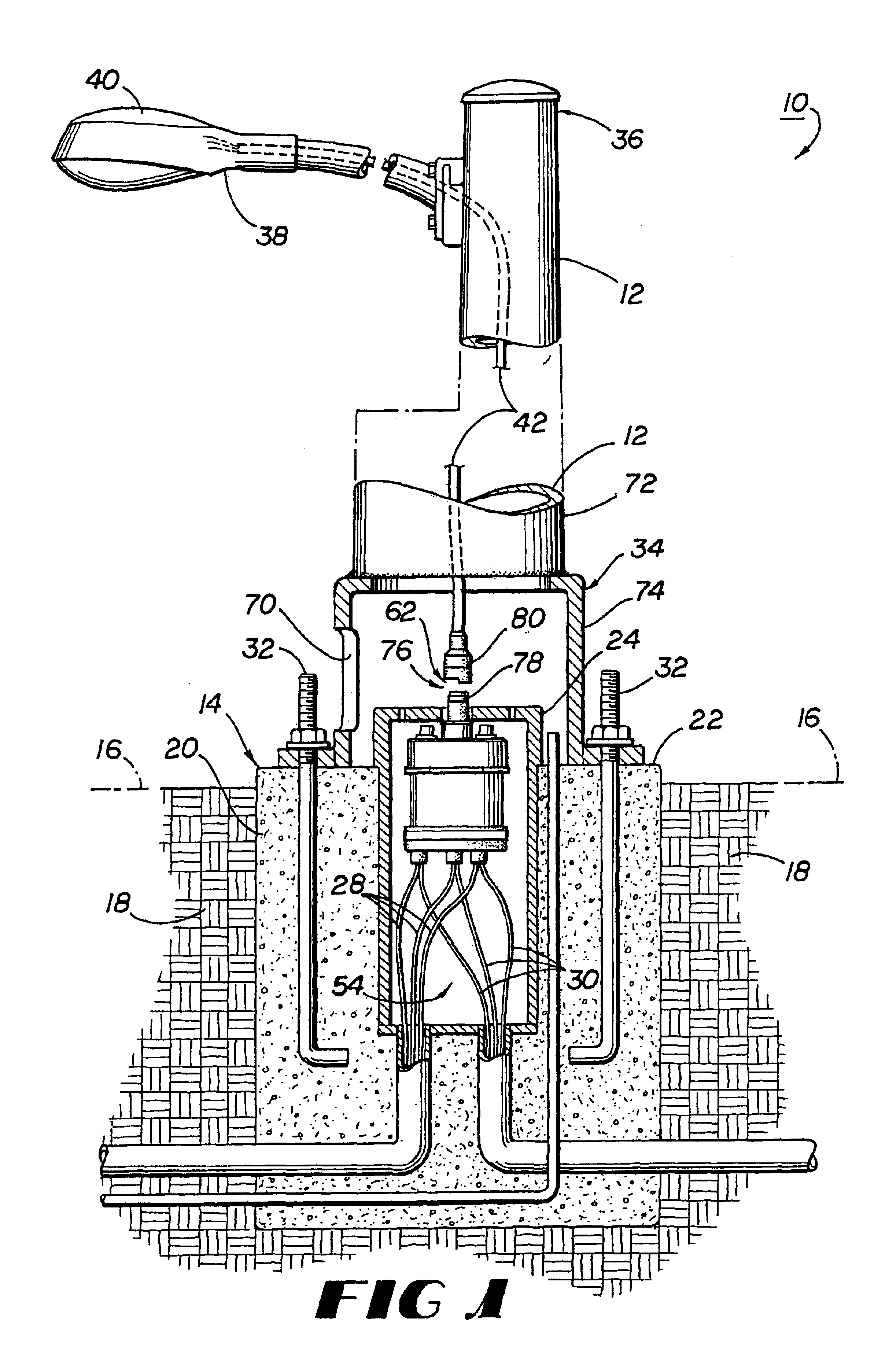
The disadvantages of the prior art are overcome by the present invention which, in one aspect, is a mast lighting system. The lighting system includes at least one conventional mast having a proximate end and an opposite distal end. The distal end is capable of supporting an electrical component, such as a street lamp, and the proximate end is mounted to a foundation, at least a portion of which has a generally plana...

Problems solved by technology

The performance of such a system is impaired by several shortcomings.
Wire and cable attachments are generally made by splices, which are vulnerable to failure when tensile forces are applied to the connections.
In catastrophic failure, such as that caused by a collision by an automobile or truck, the spliced connections are likely to disconnect, causing an interruption in service throughout the grid, and exposing dangerously “hot” wires.
Such a system requires significantly greater expense and space to install, as a remote hole must be dug and maintained for each lighting unit within the grid, and additional cable is required to accommodate the remotely located electrical components.

Method used


Image

  • Mast lighting system
  • Mast lighting system
  • Mast lighting system

Examples


first embodiment

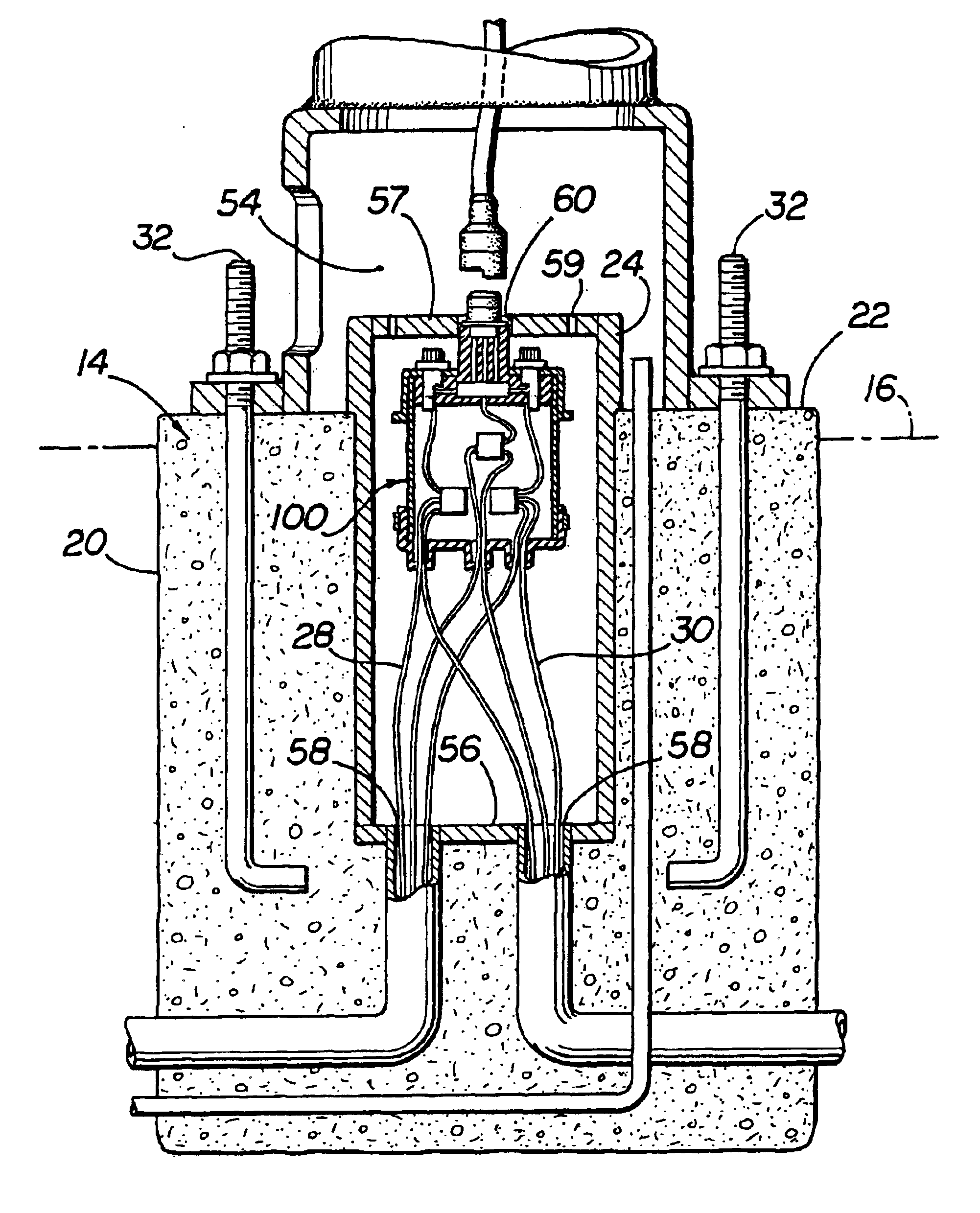
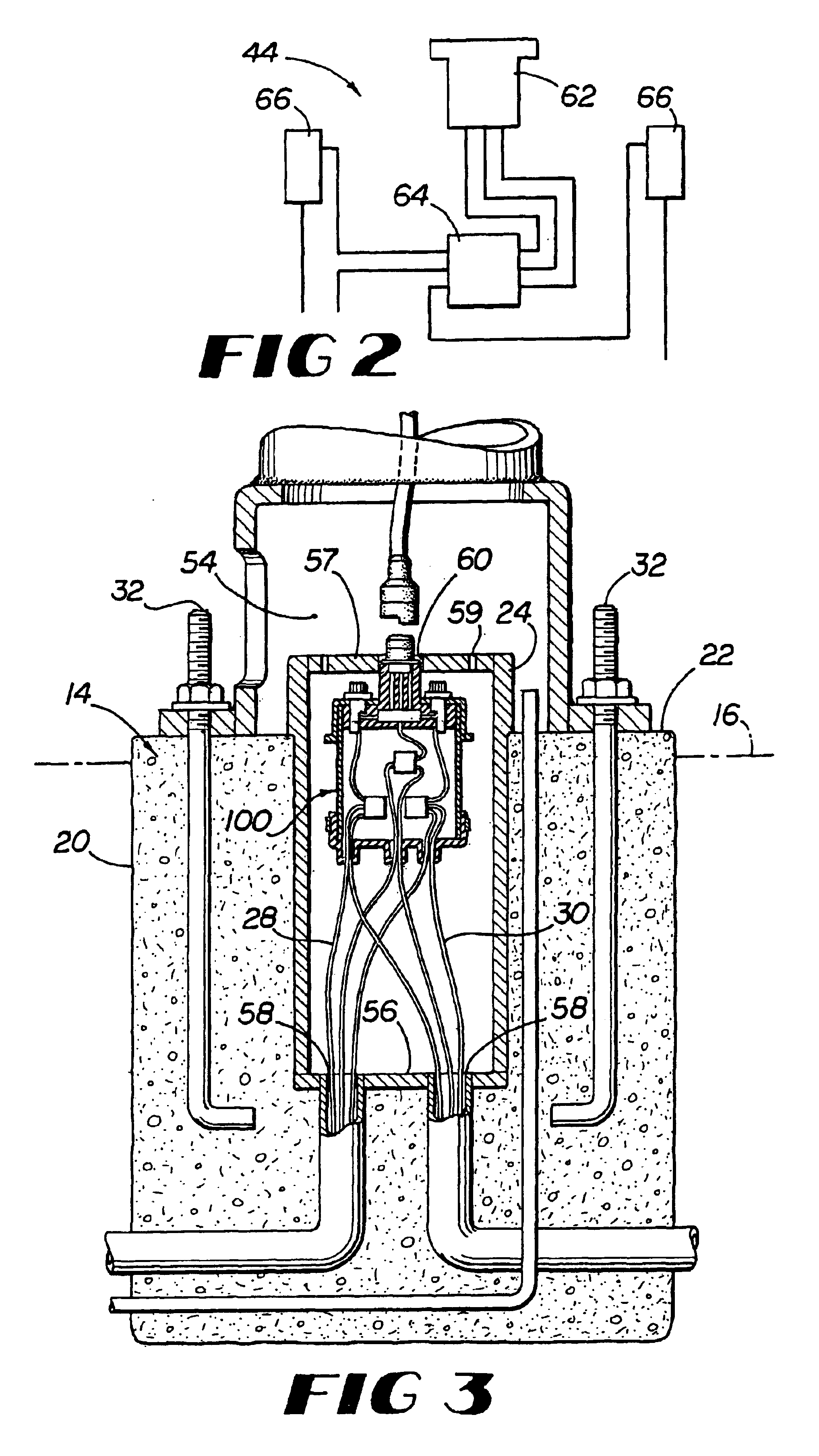
In a first embodiment, referring now to FIGS. 3-4C, a casing 100 is provided within chamber 54, the casing 100 defining a space therein capable of enclosing the distribution component subassembly 44. The casing 100 may be watertight, such that unwanted moisture and corrosive effects on the distribution component subassembly 44 are minimized. A selected one of the male plug 80 or female inlet 78 is electrically connected to the distribution component subassembly 44 and may be mounted on the casing 100. The casing 100 defines an aperture 102 therein, and includes a closure member 104 which covers the aperture 102 and provides a watertight seal.

The casing 100 may be of any desired shape. In one example, the casing 100 is made up of a pot 106 having the aperture 102 therein, and, as seen in FIGS. 4B and 4C, a cap 108 which makes up the closure member 104, covering and sealing the aperture 102. The pot 106 has a substantially cylindrical body 110 having a closed end 112 and an opposite o...

second embodiment

Referring now to FIGS. 6-11, the mast lighting system 10 is shown. Here, a power distribution assembly 200 is provided that has a casing 210 and a distribution component subassembly 44 disposed within an interior 212 of the casing. The casing has an upper portion 214, a bottom portion 216, a side wall 218, and defines a plurality of openings 220. In one aspect, the plurality of openings includes a first opening 222 and a second opening 224. The first opening may be defined in the upper portion 214 of the casing 210 and the second opening may be defined in the bottom portion 216 of the casing. In one example, the bottom portion 216 of the casing is substantially planar.

The power distribution assembly may include an electrical cable 240 that is in communication with the distribution component assembly 44. In one example, a portion of the electrical cable passes through the second opening 224. Due to the potentially adverse weather conditions to which the power distribution assembly wo...


PUM


Abstract

A mast lighting system of the type including at least one mast that is mountable onto a foundation. A portion of the mast is capable of supporting an electrical component. A distribution component subassembly is disposed within a power distribution assembly. An electrical cable disposed within the mast connects the electrical component to the distribution component subassembly of the power distribution assembly through a breakaway connector set. A remote power source is in communication with the distribution component subassembly. The mast defines an interior chamber therein of sufficient dimensions to receive the power distribution assembly. The power distribution assembly is disposed within the chamber and onto a generally planar surface of the foundation. In use, the power distribution assembly is protected from collision damage, but is accessible to the user through the opening in the mast.

Description

BACKGROUND1. Field of the InventionThe invention relates to mast mounted outdoor lighting systems for illuminating roadways, sidewalks, parking lots or the like, and specifically to a mast mounted lighting system having a power distribution assembly may be stored within the base of the mast and is readily accessible by the user through the base of the mast.2. Background ArtOutdoor mast lighting systems are well known in the prior art. Such systems commonly are supported above the surface to be lighted by a long pole or mast. Masts are typically hollow, and may be round, square or of any selected cross-sectional shape which provides adequate stability. The mast may include a breakaway base at its lower end having an opening (or “handhole”) therein, through which the interior of the mast may be accessed by maintenance or installation personnel. The mast is mounted on a foundation of concrete or other suitable material set permanently into the ground and may be affixed to the foundatio...

Claims


Application Information

Patent Timeline
IPC IPC(8): E04H12/00H02G3/18F21S8/08F21V23/02F21V27/00
CPCE04H12/003F21S8/086H02G3/185F21V27/00F21W2131/103F21V23/02
Inventor GINSBURG, THOMAS A.
Owner GINSBURG THOMAS A
Learn More