
Optical transducer

Inactive Publication Date: 2005-03-29
WIRTHLIN ALVIN R
View PDF27 Cites 21 Cited by
  • Summary
  • Abstract
  • Description
  • Claims
  • Application Information

AI Technical Summary

Problems solved by technology

Such sensors are prone to wear, mechanical and / or electrical breakdown or, at the very least, inaccurate liquid level detection.
Although variable capacitance probes have been developed to overcome these drawbacks, they are cost-prohibitive in many applications and are typically limited to measure a certain type of liquid, since different liquids will have different dielectric properties.
Although these transducers work well for their intended function, they are relatively heavy, difficult to manufacture, and high in cost, making them impractical for many low-cost applications.
These types of transducers can be relatively difficult and costly to manufacture and their resolution is typically limited by the number of bars in the circumferential track, the spacing between bars, the relative size of the transducers, and other factors.

Method used


Image

  • Optical transducer
  • Optical transducer
  • Optical transducer

Examples


Embodiment Construction

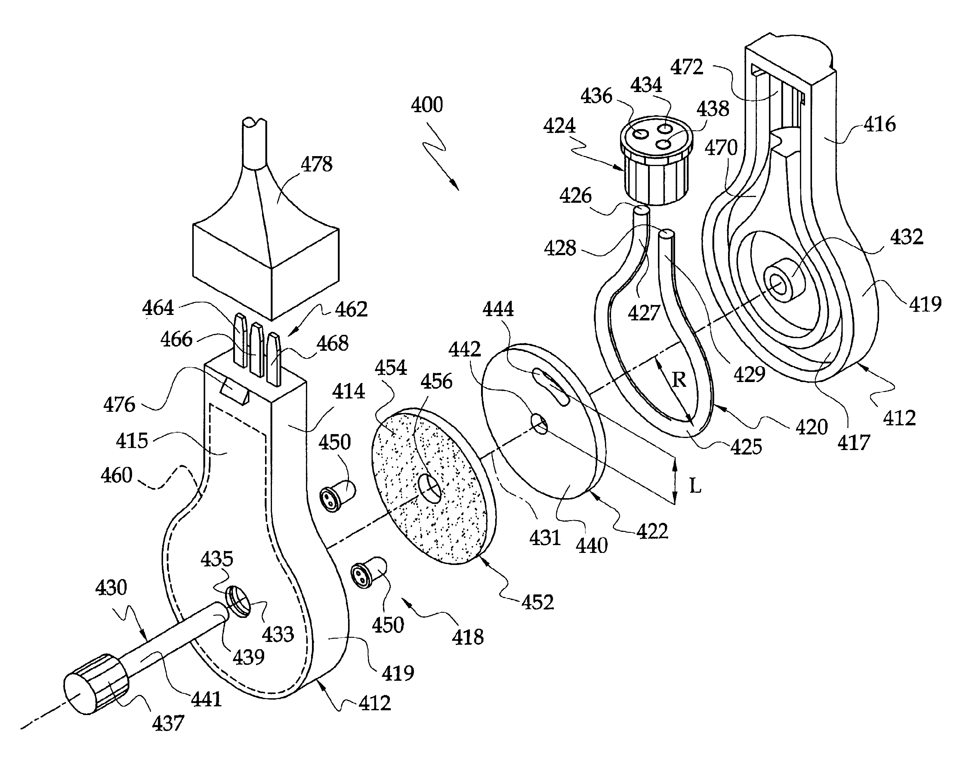
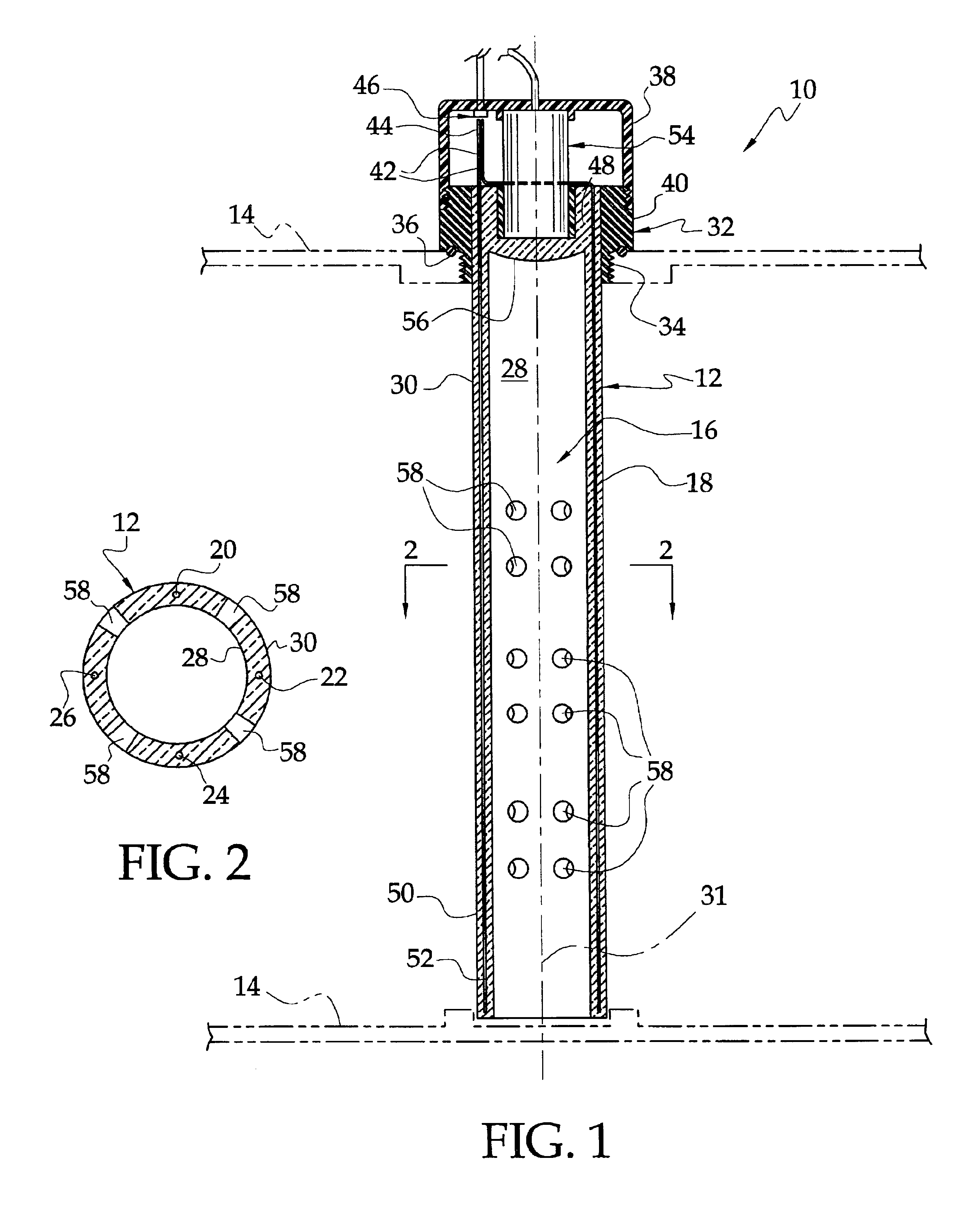
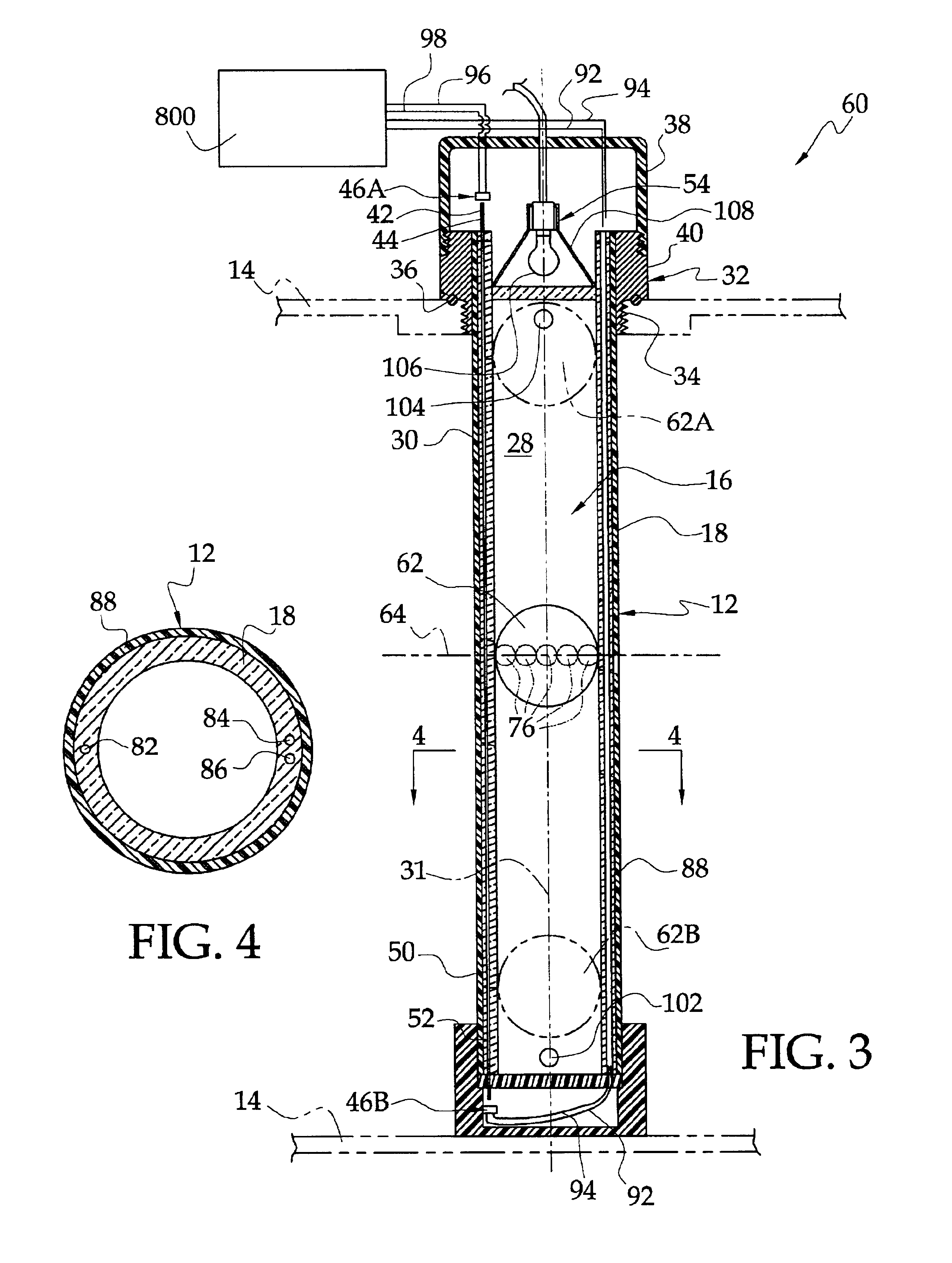
Referring now to the drawings, and to FIGS. 1 and 2 in particular, a fluid level transducer 10 according to the present invention is illustrated. The fluid level transducer 10 includes an elongate tubular member or housing 12 that is adapted for mounting in a container 14 (shown in phantom line), such as the fuel tank of a motor vehicle. The tubular member 12 includes a central bore 16 and has a continuous wall 18 that surrounds the central bore. The tubular member 12 is preferably constructed of transparent or translucent material that is resistant to the liquid in which it is to be immersed. A plurality of conduits 20, 22, 24, and 26 are preferably formed at equally spaced circumferential intervals in the wall 18 of the tubular member between an inner wall surface 28 and an outer wall surface 30, and extend generally parallel to a central axis 31 of the tubular member. The conduits can be formed simultaneously with the tubular member during extrusion or other molding processes. Al...


PUM


Abstract

An optical transducer comprises a light source for emitting radiant energy, a base member, and an elongate light collector positioned for receiving radiant energy from the light source. The elongate light collector comprises a tunnel formed in the base member and a collector window that extends along a length of the tunnel. Radiant energy projected by the light source is received in the tunnel through the window and is transmitted along a length of the tunnel. A portion of the transmitted radiant energy exits the tunnel to thereby vary the intensity of light along the tunnel length. At least one photosensor is positioned for detecting the amount of radiant energy at a location in the tunnel. In this manner, the intensity of radiant energy at the tunnel location is indicative of at least relative position between the incident radiant energy and the at least one photosensor.

Description

BACKGROUND OF THE INVENTION1. Field of the InventionThis invention relates to optical transducers, and more particularly to optical transducers for determining position, orientation, direction, revolution, acceleration, fluid flow, fluid level, torque, pressure, opacity, and the like.2. Description of the Related ArtTransducers for determining linear or angular position along one or more axes, orientation, direction, revolution, acceleration, fluid flow, fluid level, torque, pressure, and the like, are often used in vehicles, industrial equipment and other systems and components. Such transducers typically operate by detecting a change in an electrical property of the transducer, such as a change in resistance, capacitance, current flow, magnetic field, and so on, and may be embodied by variable capacitor or resistor mechanisms, optical systems, or Hall effect sensors.By way of example, prior art liquid level sensors, such as fuel sensors for motor vehicles, usually include a float ...

Claims


Application Information

Patent Timeline
IPC IPC(8): G01P15/08G01F23/68G01C9/06G01P3/36G01F23/30G01F23/292G01C9/00G01P15/093G01P13/00G01D5/26G01F23/284G01P15/00G01D5/353G01F23/28
CPCG01C9/06G01D5/26G01F23/292G01F23/2922G01P15/093G01F23/686G01P3/36G01P13/002G01P15/006G01P15/0888G01F23/2925G01C2009/066
Inventor WIRTHLIN, ALVIN R.
Owner WIRTHLIN ALVIN R
Learn More