Adaptive receive and omnidirectional transmit antenna array

a technology of omnidirectional transmitting and receiving antennas, applied in the field of wireless communication systems, can solve problems such as complicated power control system performance, and achieve the effects of increasing forward capacity, increasing reverse capacity, and increasing the overall number of users

Inactive Publication Date: 2005-03-29
IPR LICENSING INC
View PDF22 Cites 51 Cited by
  • Summary
  • Abstract
  • Description
  • Claims
  • Application Information

AI Technical Summary

Benefits of technology

By utilizing a horizontally polarized transmit and vertically polarized receive array, isolation between the two antennae is improved.
The use of an adaptive antenna in the subscriber unit on the receive side has the potential to increase the forward capacity to levels equal to or greater than the reverse capacity. This allows for a significant increase in the overall number of users without directly increasing the reverse capacity.
It is also envisioned that other types of systems, such as Time Division Duplex (TDD) systems, may also advantageously use the adaptive array for receive but to steer in an omnidirectional mode during transmit periods. The effect is achieves a similar result. It is also expected that when TDD systems are in a stationary or slow moving environment, a directional transmit may also be able to be utilized.

Problems solved by technology

However, employing directional antennas on the reverse link complicates the performance of power control systems.

Method used


Image

  • Adaptive receive and omnidirectional transmit antenna array
  • Adaptive receive and omnidirectional transmit antenna array
  • Adaptive receive and omnidirectional transmit antenna array

Examples


Embodiment Construction

A description of preferred embodiments of the invention follows.

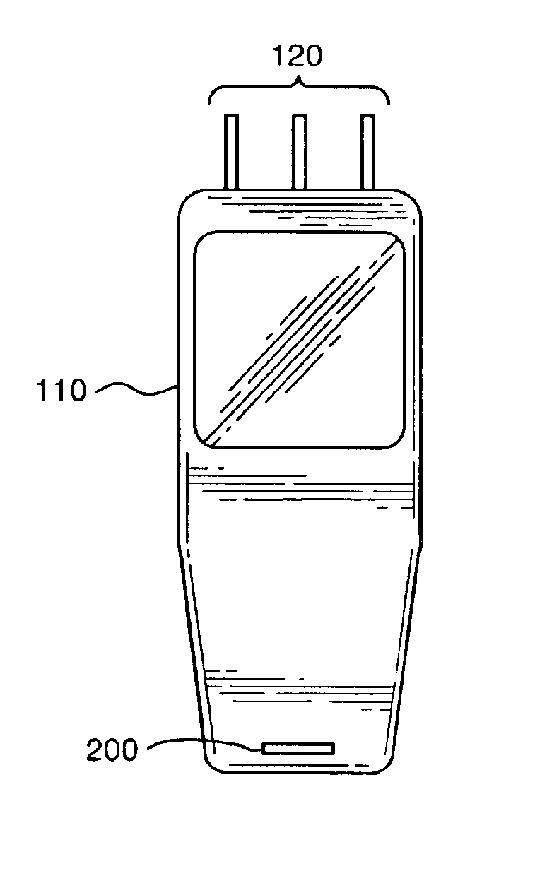
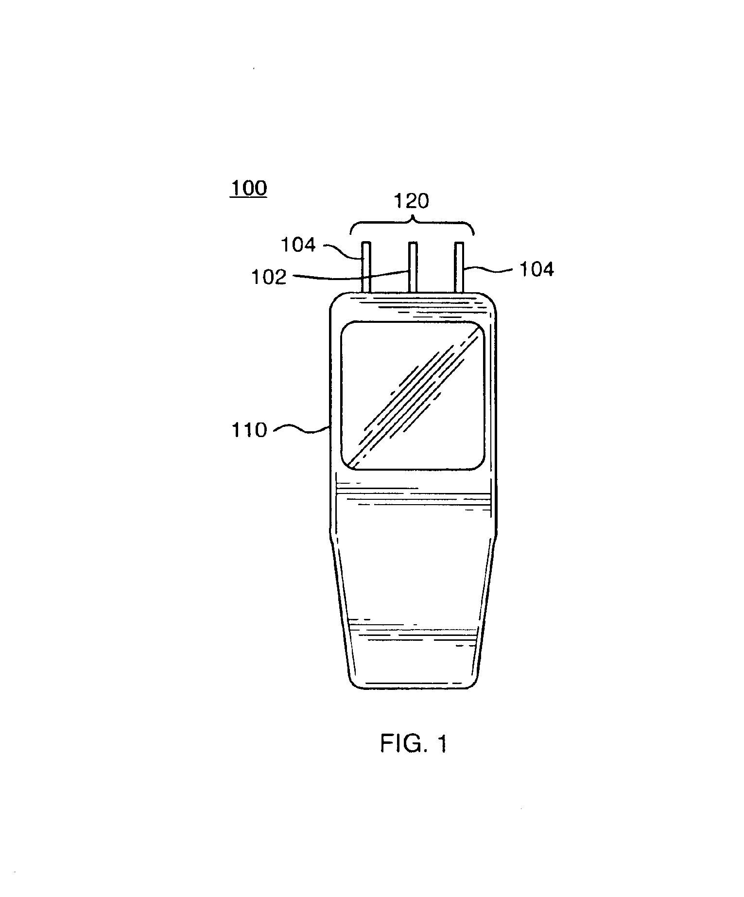
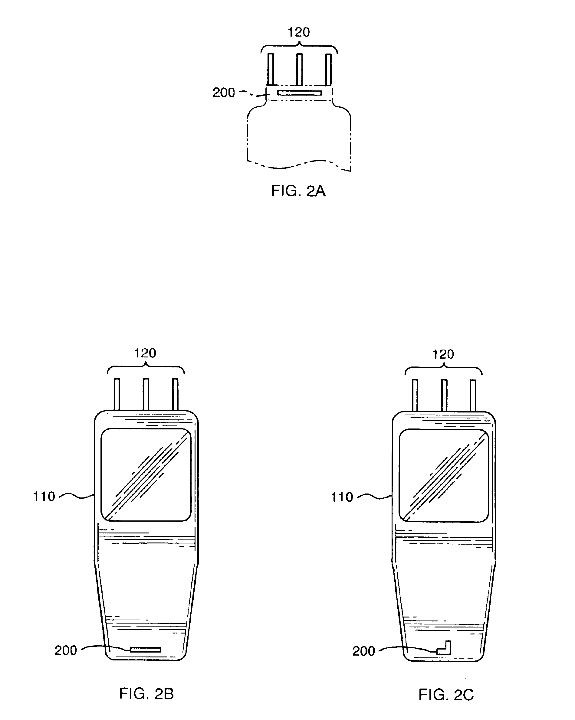
Turning attention now to the drawings, FIG. 1 illustrates a wireless device 100 that consists of a housing 110 having incorporated therein an antenna array 120. In general the device 100 is some form of wireless communications device, such as a cellular mobile handset, or a personal digital assistant such as a Palm Pilot.

The antenna array 100 provides for directional reception of forward link radio signals. The forward link signals may be transmitted from a base station, in the case of a cellular handset 100, or from a access point, in the case of a wireless data unit 100 making use of wireless local area network (WLAN) protocols. By directively receiving signals originating more or less from the location of a particular base station and / or access point, the antenna array 120 assists in reducing the overall effect of intercell interference and multipath fading for the mobile unit 100. Moreover, as will be understood sho...


PUM


Abstract

An adaptive antenna used in a receive only mode with a separate omnidirectional transmit antenna. The arrangement is especially effective for small, handheld wireless devices. The transmit antenna maybe integrated with the receive array by utilizing a horizontally polarized transmit and vertically polarized receiver ray. In other embodiments, the transmit antenna may be physically separate and not integrated with the receive array. In either case there is separate receive and transmit signal port as an interface to radio transceiver equipment. The use of an adaptive antenna in the receive only direction has the potential to increase forward links capacity to levels equal to or greater than reverse link capacity. This allows for a significant increase in the overall number of users that may be active at the same time in a wireless system.

Description

FIELD OF THE INVENTIONThis invention relates to wireless communication systems and in particular to a compact, configurable antenna apparatus for use with a portable subscriber unit.BACKGROUND OF THE INVENTIONCode Division Multiple Access (CDMA) modulation and other spread spectrum techniques now find widespread application in wireless systems such as cellular mobile telephones, wireless local area networks and similar systems. In these systems a connection is provided between a central hub or base station and one or more mobile or remote subscriber units. The base station typically includes a specialized antenna for sending forward link radio signals to the mobile subscriber units and for receiving reverse link radio signals transmitted from the mobile units. Each mobile subscriber unit also contains its own antenna, for the reception of the forward link signals and for transmission of reverse link signals. A typical mobile subscriber unit may for example, be a digital cellular tel...

Claims


Application Information

Patent Timeline
Patent Type & Authority Patents(United States)
IPC IPC(8): H01Q1/24H04M1/00H01Q1/38H01Q1/52H01Q3/26H01Q3/44H01Q9/30H01Q9/42H01Q19/32H01Q21/24H01Q25/00H04B1/38H04B7/10H04B7/26H04J99/00
CPCH01Q1/242H01Q1/243H01Q1/245H01Q1/38H01Q1/521H01Q3/2605H04B7/10H01Q9/30H01Q9/42H01Q19/32H01Q21/24H01Q25/001H01Q25/002H01Q3/44H01Q1/24H04B1/40
Inventor PROCTOR, JR., JAMES A.CHIANG, BING
Owner IPR LICENSING INC
Why Eureka
Try Eureka