

Protective relay system
a relay system and relay technology, applied in the direction of emergency protective circuit arrangement, electrical equipment, emergency protection circuit arrangement, etc., can solve the problem that the circuit breaker can be tripped against the internal fault, and achieve the effect of reliable elimination of the fault poin
- Summary
- Abstract
- Description
- Claims
- Application Information
AI Technical Summary
Benefits of technology
Problems solved by technology
Method used
Image

Examples
first embodiment
(First Embodiment)
A protective relay system according to a first embodiment of the present invention will now be described with reference to FIGS. 1 and 2.
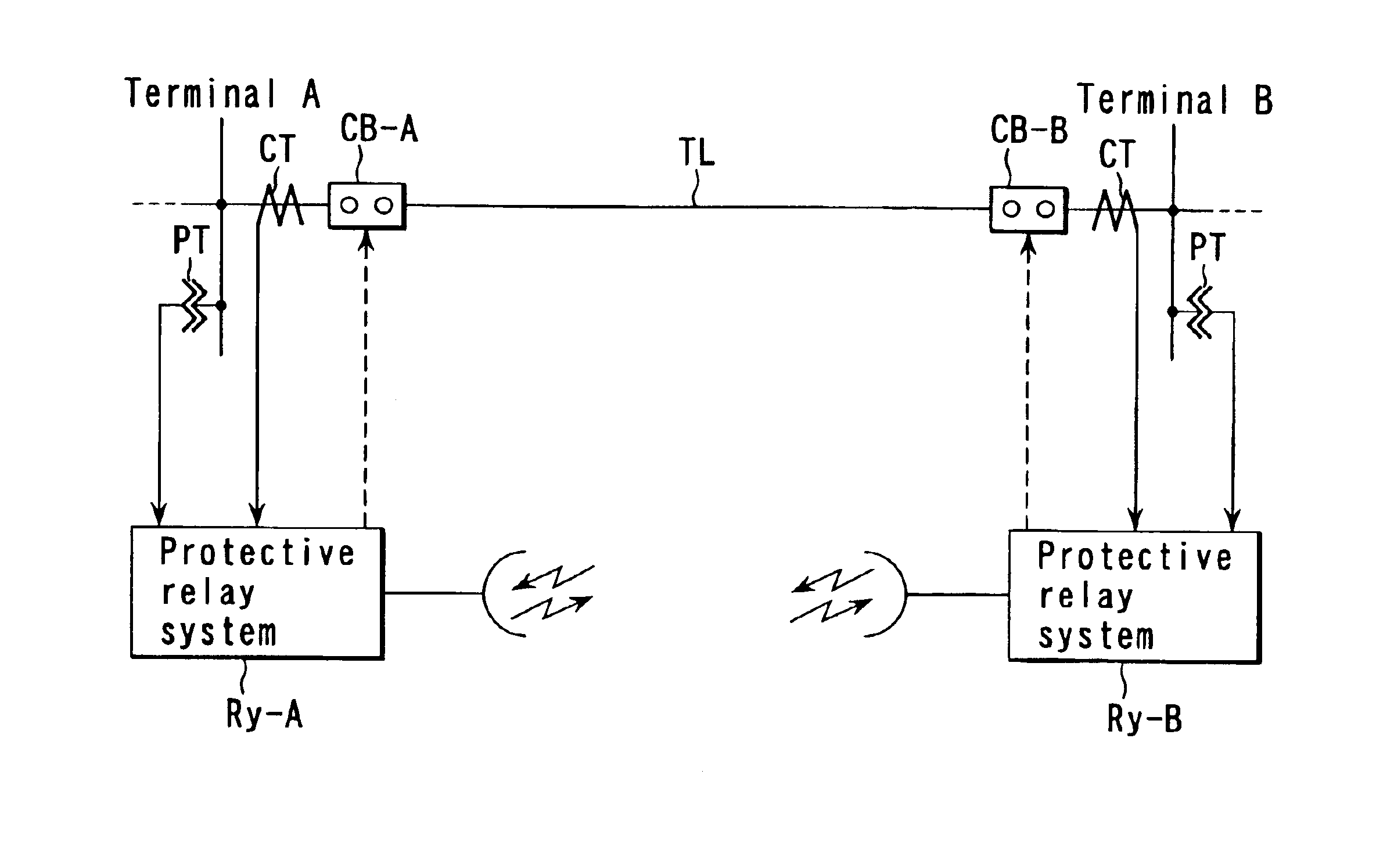
In FIG. 1, TL indicates a power transmission line for interconnecting terminals A and B of a power system, which is to be protected. Protective relay systems Ry-A and Ry-B for protecting the transmission line upon receipt of current I and voltage V from a current transformer CT and a voltage transformer PT are provided at the terminals A and B, respectively.
The protective relay systems Ry-A and Ry-B have the same configuration. The internal configuration of the protective relay system Ry-A will be described as a representative example.
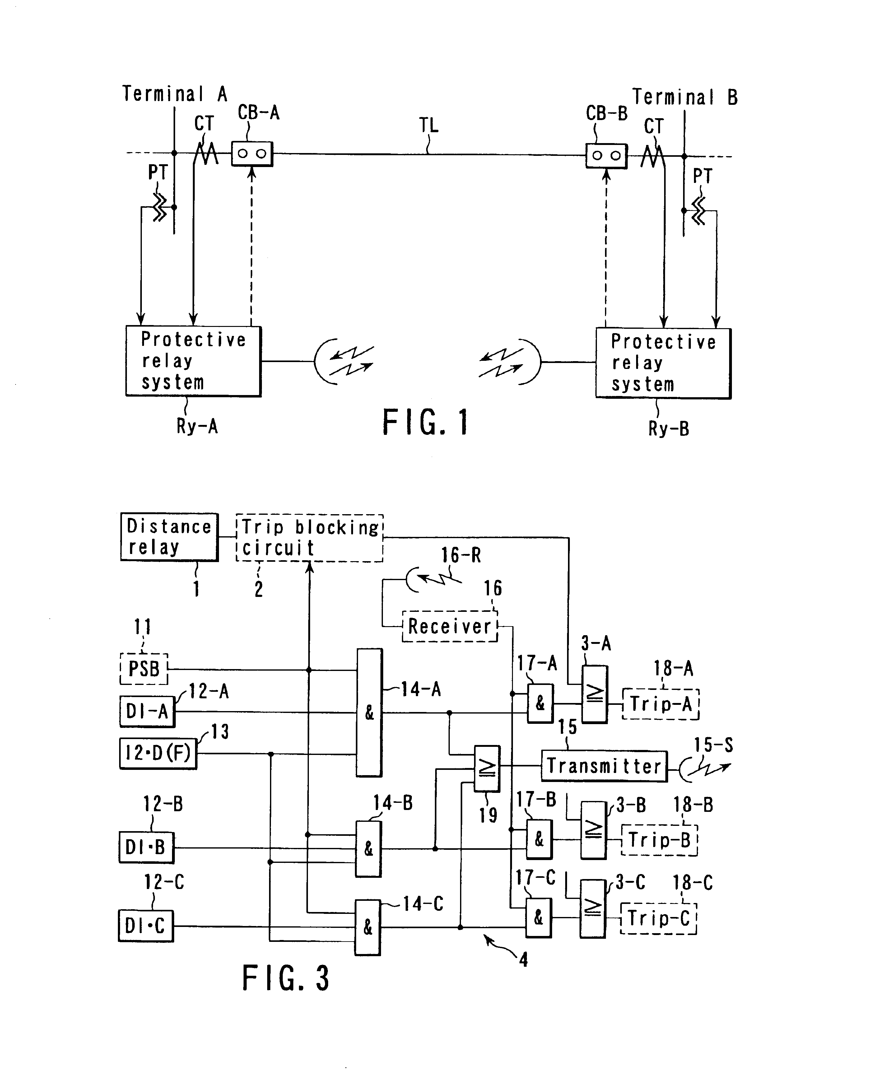
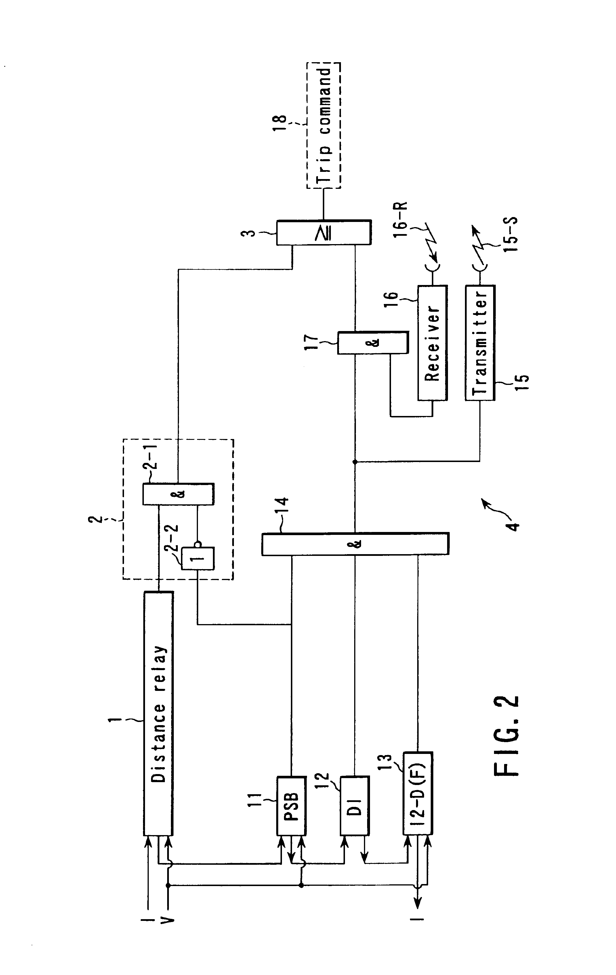
FIG. 2 is a block diagram showing the protective relay system Ry-A of FIG. 1 in detail.
In FIG. 2, reference numeral 1 denotes a distance relay serving as a main protective relay system. The distance relay 1 performs a distance-measuring operation based on the voltage and current received from the ter...
second embodiment
(Second Embodiment)
A protective relay system according to a second embodiment of the present invention will now be described with reference to FIG. 4. The same elements (relays and logic circuits) as those of the first embodiment are denoted by the same reference numerals and their descriptions are omitted.
The second embodiment shown in FIG. 4 differs from the first embodiment shown in FIG. 2 in that a fault detection circuit 20 indicated by the broken line is used in place of the current change detection relay 12 shown in FIG. 2. Since the other elements have been described above, only the circuit 20 will be described here.
In FIG. 4, reference numeral 21 indicates an undervoltage relay UV. The relay 21 operates when a system voltage becomes not higher than a set value due to a close-end fault. Only one undervoltage relay is shown in FIG. 4. Actually, it is desirable to arrange both a phase voltage UV for detecting a ground fault and a line-to-line voltage UV for detecting a short-c...
third embodiment
(Third Embodiment)
A protective relay system according to a third embodiment of the present invention will now be described with reference to FIG. 5. The same elements (relays and logic circuits) as those of the first and second embodiments are denoted by the same reference numerals and their descriptions are omitted.
The protective relay system according to the third embodiment is configured by a combination of the relays shown in FIG. 2 and FIG. 4. The protective relay system detects a system fault if any one of four relays of zero-phase-sequence overcurrent relay 22, negative-phase-sequence overcurrent relay 23, current change detection relay 12, and undervoltage relay 21 operates. The system fault can thus be detected with higher precision.
PUM
 Abstract
Description
Claims
Application Information