Optical fiber tape with optical fiber array

a technology of optical fiber and optical fiber strips, which is applied in the direction of optical elements, cables, instruments, etc., can solve the problems of increasing the probability of work errors, requiring a prolonged work time, and work trouble, so as to minimize the microbending of optical fibers

Inactive Publication Date: 2005-03-29
NEC CORP
View PDF2 Cites 19 Cited by
  • Summary
  • Abstract
  • Description
  • Claims
  • Application Information

AI Technical Summary

Benefits of technology

Accordingly, it is an object of the invention to provide a tape optical fiber cord with an optical fiber array which, even when a tape fiber, in which a plurality of optical fibers have been arranged, has been bent in its portion between both ends thereof, local microbending of the optical fibers can be minimized.
As defined in the above item (6), the protective tube may be fixed at the predetermined position or a position near the predetermined position. Alternatively, the protective tube may be fixed to the fiber array on its fixation side which is the opposite side of the predetermined position. When any one end of the protective tube is a free end, the degree of freedom of the protective tube can be ensured.

Problems solved by technology

This makes the work troublesome, requires a prolonged work time, and, at the same time, increases the probability of the incidence of mistakes in the work.
The conventional fiber cord 111 with a half pitch fiber array shown in FIG. 5, however, has a problem that, since one end thereof is fixed to the branching case 132, microbends often occur.
When microbends occur, light propagated through the core is leaked out from the microbends to the outside of the optical fiber, leading to transmission loss.

Method used


Image

  • Optical fiber tape with optical fiber array
  • Optical fiber tape with optical fiber array
  • Optical fiber tape with optical fiber array

Examples


Embodiment Construction

Preferred embodiments of the tape optical fiber cord with an optical fiber array according to the invention will be explained in detail in conjunction with the accompanying drawings.

<First Preferred Embodiment>

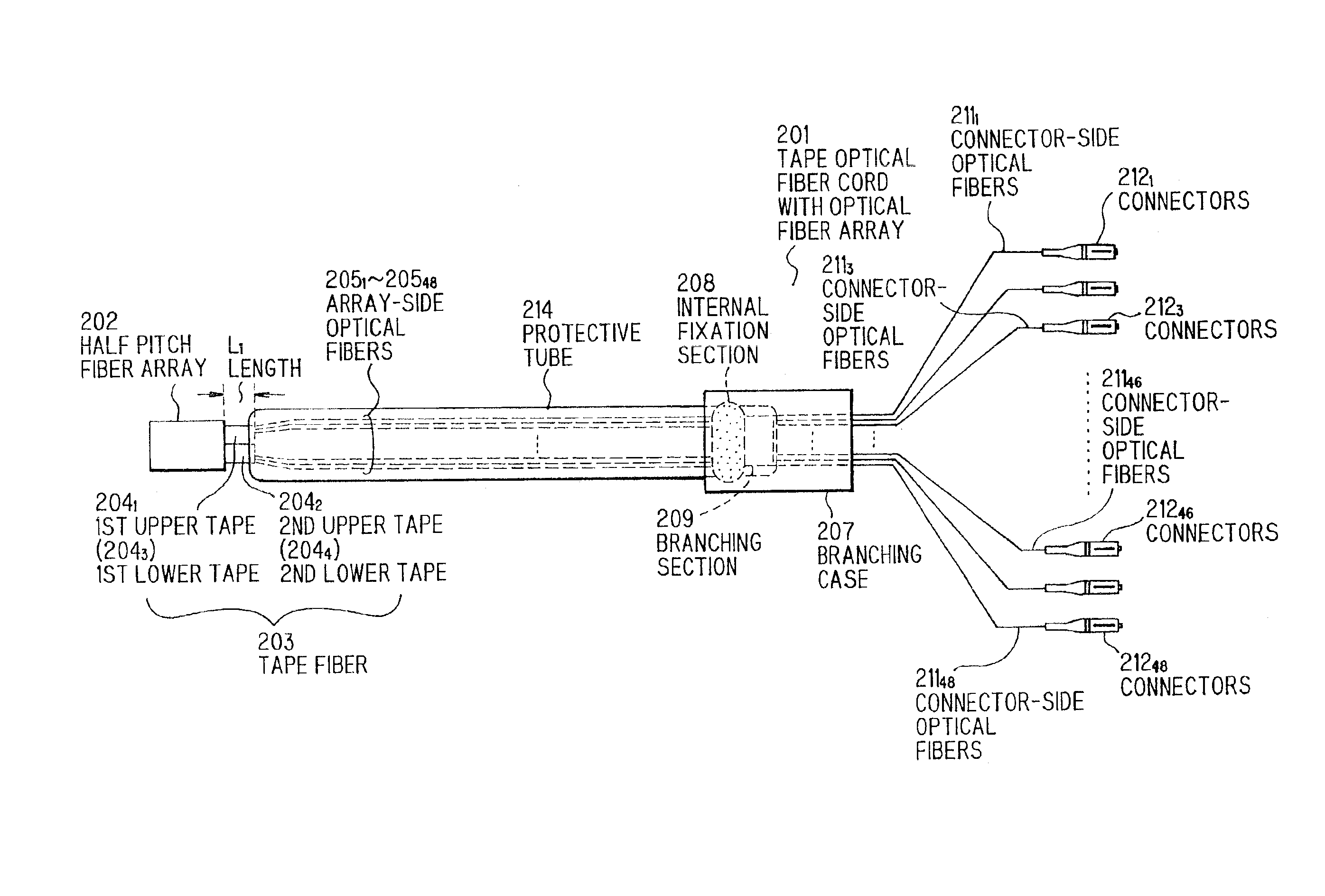
FIG. 8 shows a tape optical fiber cord with an optical fiber array in the first preferred embodiment of the invention. A tape optical fiber cord 201 with an optical fiber array has on its one end a half pitch fiber array 202 connected to an optical waveguide (not shown). One end of a tape fiber 203 in two columns of two stages is fixed to the half pitch fiber array 202. This tape fiber 203 comprises tapes arranged in two columns of two stages, i.e., a first upper tape 2041, a second upper tape 2042, a first lower tape 2043, and a second lower tape 2044 each comprising 12-core tape core. In FIG. 8, however, only the first upper tape 2041 and the second upper tape 2042 are shown, and two tapes of the first lower tape 2043 and the second lower tape 2044 are hidden respective...


PUM

PropertyMeasurementUnit
sectional structureaaaaaaaaaa
sizeaaaaaaaaaa
timeaaaaaaaaaa

Abstract

A tape optical fiber cord with an optical fiber array has, at its one end, a half pitch fiber array connected to an optical waveguide. Connectors are connected respectively to connector-side optical fibers located at the other end of the tape optical fiber cord. A branching case for branching the connector-side optical fibers is provided in a position between both ends of the cord. One end of a tape fiber comprising tapes arranged in two columns of two stages is fixed to the half pitch fiber array, and the other end is fixed in a fixation section within the branching case to the case. In the portion intermediate between the two fixed portions, the connector-side optical fibers are separated one by one, and the outside of the separated optical fibers is covered with a protective tube while leaving a space between the protective tube and the separated optical fibers. By virtue of the above construction, the tape optical fiber cord with an optical fiber array can minimize the occurrence of microbends in a local potion of the optical fibers even when a portion between both ends of a tape, in which a plurality of optical fibers have been arranged, has been bent, because the optical fibers are deformed independently of one another upon the application of external force and, thus, any excessive stress is not applied to the optical fibers.

Description

FIELD OF THE INVENTIONThe invention relates to a tape optical fiber cord with an optical fiber array as a tape optical fiber cord to which an optical fiber array has been attached, and more particularly to a tape optical fiber cord with an optical fiber array which can reduce the occurrence of microbends.BACKGROUND OF THE INVENTIONThe spread of the Internet and an increase in the capacity of data to be transmitted have led to a massive increase in traffic. This tendency has led to energetic development of technology for increasing the capacity of optical wavelength multiplex communication systems.When devices constituting a communication system are connected to each other through a plurality of optical fibers, a method, wherein a bundle of a plurality of optical fibers is provided and is used for connection between these devices, is in many cases more convenient than a method wherein the devices are connected to each other by separately drawing these optical fibers one by one. In th...

Claims


Application Information

Patent Timeline
Patent Type & Authority Patents(United States)
IPC IPC(8): G02B6/06G02B6/38G02B6/44H01B11/00
CPCG02B6/06G02B6/4475G02B6/3878
Inventor NAKAYA, KEN-ICHI
Owner NEC CORP
Why Eureka
Try Eureka