
Cooling system for protective vest

a technology of cooling system and protective vest, which is applied in the field of protective vests, can solve the problems of affecting the evaporation of sweat, posing the risk of serious injury, and the comfort of protective vests, and achieve the effect of improving the cooling capacity

Active Publication Date: 2005-04-05
FORGACH PAUL A
View PDF26 Cites 19 Cited by
  • Summary
  • Abstract
  • Description
  • Claims
  • Application Information

AI Technical Summary

Benefits of technology

For improved cooling capacity, a second fan can be supported at the upper end of the elongated housing adjacent the first fan, and a second electric motor can be supported proximate the upper end of the elongated housing and coupled to the second fan for rotating the second fan. The aforementioned electrical wires can be coupled in parallel with the second electric motor to power both fans simultaneously, or the fans can be controlled individually.
The cooling method described above can be further enhanced by supporting a second fan at the upper end of the elongated housing, providing a second electric motor for rotating the second fan, and supplying electrical power to the second electric motor for rotating the second fan.

Problems solved by technology

However, during summer months in the Southern and Southwestern regions of the United States, such protective vests can become extremely uncomfortable, trapping body heat and moisture, and interfering with the evaporation of sweat.
In some cases, officers become so uncomfortable that they remove such protective vests, posing the risk of serious injury in the event of an unexpected confrontation with a violent subject.
However, the apparatus disclosed by Frank does not appear to have any mechanism to forcibly circulate such air through such conduit.
However, no mechanism is provided for cooling the officer once the officer leaves the vehicle.
However, none of the devices described above are adapted to be quickly and easily inserted or removed, while at the same time being self-contained for use both inside and outside of a vehicle.
Moreover, none of the devices described above is easily adjustable to suit the specific needs of a particular user.
In addition, the devices described above are relatively expensive, or require significant modification of the design of existing bullet proof vests.

Method used


Image

  • Cooling system for protective vest
  • Cooling system for protective vest
  • Cooling system for protective vest

Examples


Embodiment Construction

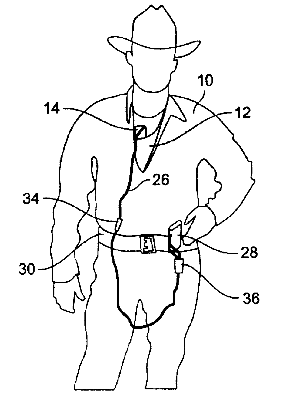
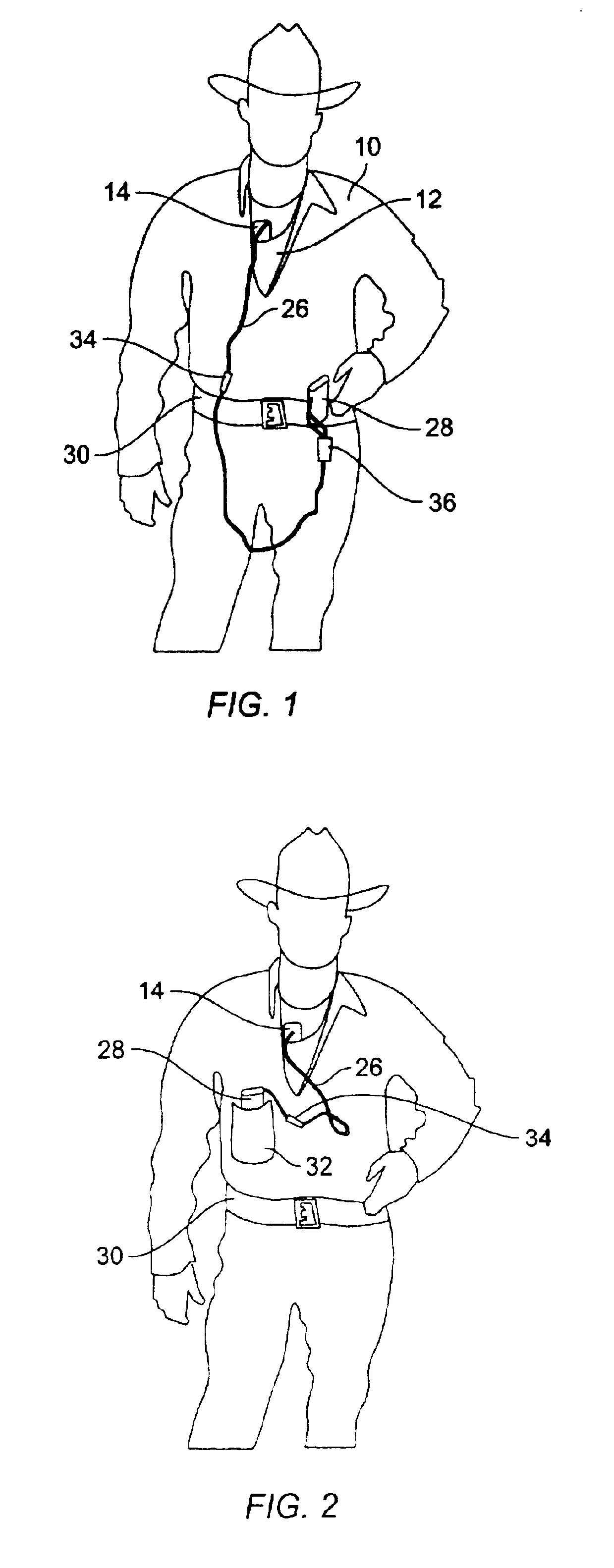
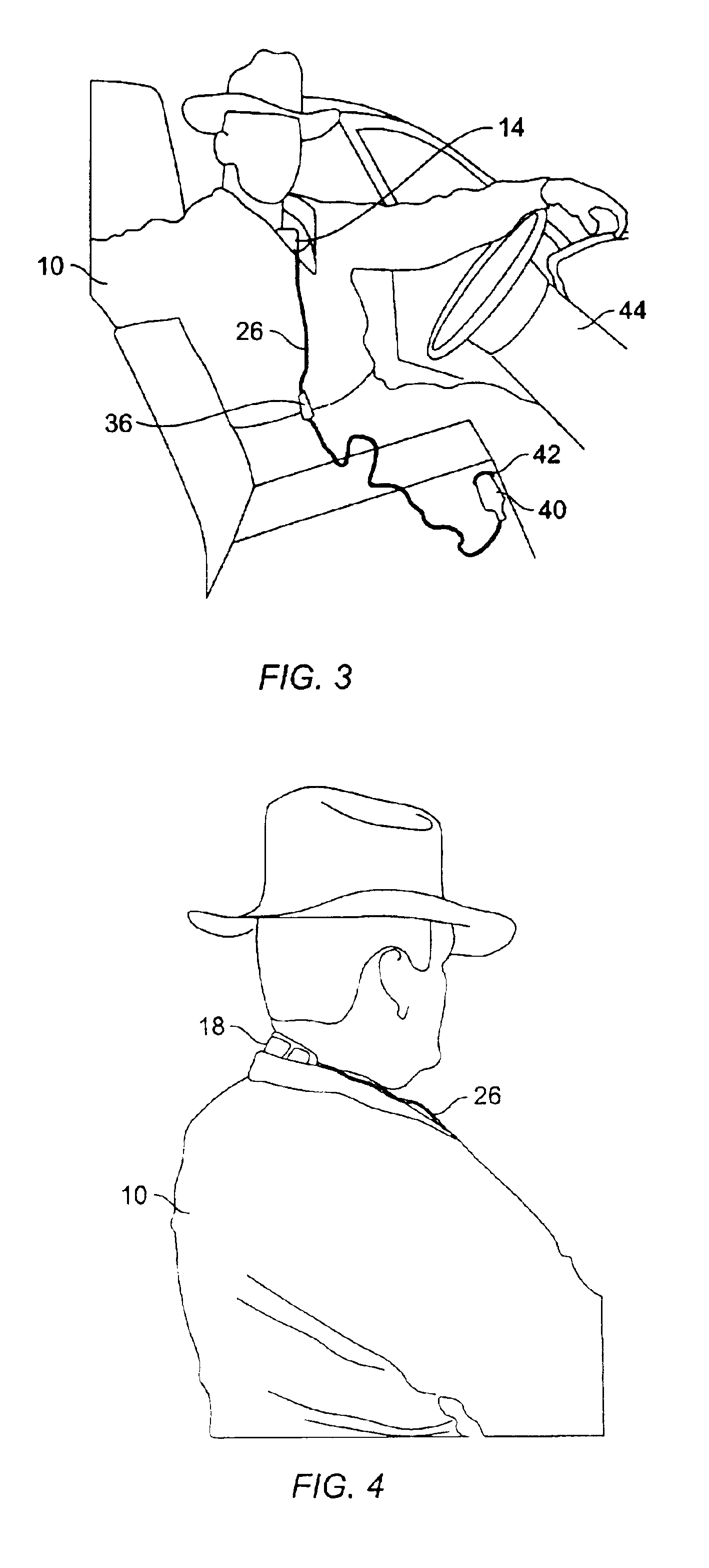
FIG. 1 illustrates a cooling system for a protective vest in accordance with one preferred embodiment of the present invention. Within FIG. 1, the user is identified generally by reference numeral 10, the protective vest by reference numeral 12, and the cooling device by reference numeral 14. Cooling device 14 includes an elongated housing 16 (see FIG. 5) disposed inside protective vest 12. A fan 18 (see FIG. 5) is supported at the upper end 20 of elongated housing 16; as shown in FIG. 1, fan 18 extends just outside the neck opening of protective vest 12 for drawing in fresh air. Within both FIGS. 1 and 2, fan 18 extends outside the neck opening of protective vest 12 just in front of the neck of user 10. Turning briefly to FIG. 4, fan 18 may alternately extend outside the neck opening of protective vest 12 just behind the neck of user 10.

Fan 18 is rotated by an electric motor 22 supported proximate upper end 20 of elongated housing 16. Preferably, motor 22 is integral with fan 18, a...


PUM


Abstract

A protective vest includes a cooling system including an elongated housing generally disposed inside the protective vest. At least one fan powered by an electric motor is supported at the upper end of the elongated housing proximate the neck opening of the protective vest for drawing fresh air into the upper end of the elongated housing. The elongated housing includes a retractable extension for varying the length thereof. Ventilation holes are formed in the elongated housing to discharge fresh air between the protective vest and the user's body. Electrical wires extend from the motor to a battery worn by the user, or to a vehicle cigarette lighter, to supply power to the motor. The electrical wires incorporate a quick-disconnect coupling and a switch / dimmer control to control the speed of the fan.

Description

BACKGROUND OF THE INVENTION1. Field of the InventionThe present invention relates generally to protective vests or other enclosures worn about a person's upper torso, and more particularly, to a cooling mechanism and related method for cooling the body of a user wearing such a protective vest.2. Description of the Related ArtTo help prevent fatal injuries to law enforcement officers, many police and other law enforcement departments mandate that officers where a protective bulletproof vest while on duty. However, during summer months in the Southern and Southwestern regions of the United States, such protective vests can become extremely uncomfortable, trapping body heat and moisture, and interfering with the evaporation of sweat. In some cases, officers become so uncomfortable that they remove such protective vests, posing the risk of serious injury in the event of an unexpected confrontation with a violent subject.Those skilled in the art have in the past attempted to solve such p...

Claims


Application Information

Patent Timeline
IPC IPC(8): A41D13/002A62B17/00
CPCA41D13/0025A62B17/005A41D13/02F41H1/02
Inventor FORGACH, PAUL A.
Owner FORGACH PAUL A
Learn More