Combustion method and apparatus for NOx reduction

Inactive Publication Date: 2005-04-05
MIURA COMPANY LIMITED
View PDF5 Cites 32 Cited by
  • Summary
  • Abstract
  • Description
  • Claims
  • Application Information

AI Technical Summary

Benefits of technology

An object of the present invention is to provide a combustion method for NOx reduction, as well as an a

Problems solved by technology

However, excessive fulfilment of this functional enhancement would cause an increase in pressure loss or an unstable combustion such as oscillating combustion.
However, this functional enhancement would cause an amplification of unstable characteristics of exhaust gas recirculation.
Increasing the exhaust-gas recirculation rate would cause these unstable characteristics to be amplified, so that stable NOx reduction could not be achieved.
Furthermore, the func

Method used


Image

  • Combustion method and apparatus for NOx reduction
  • Combustion method and apparatus for NOx reduction
  • Combustion method and apparatus for NOx reduction

Examples


Embodiment Construction

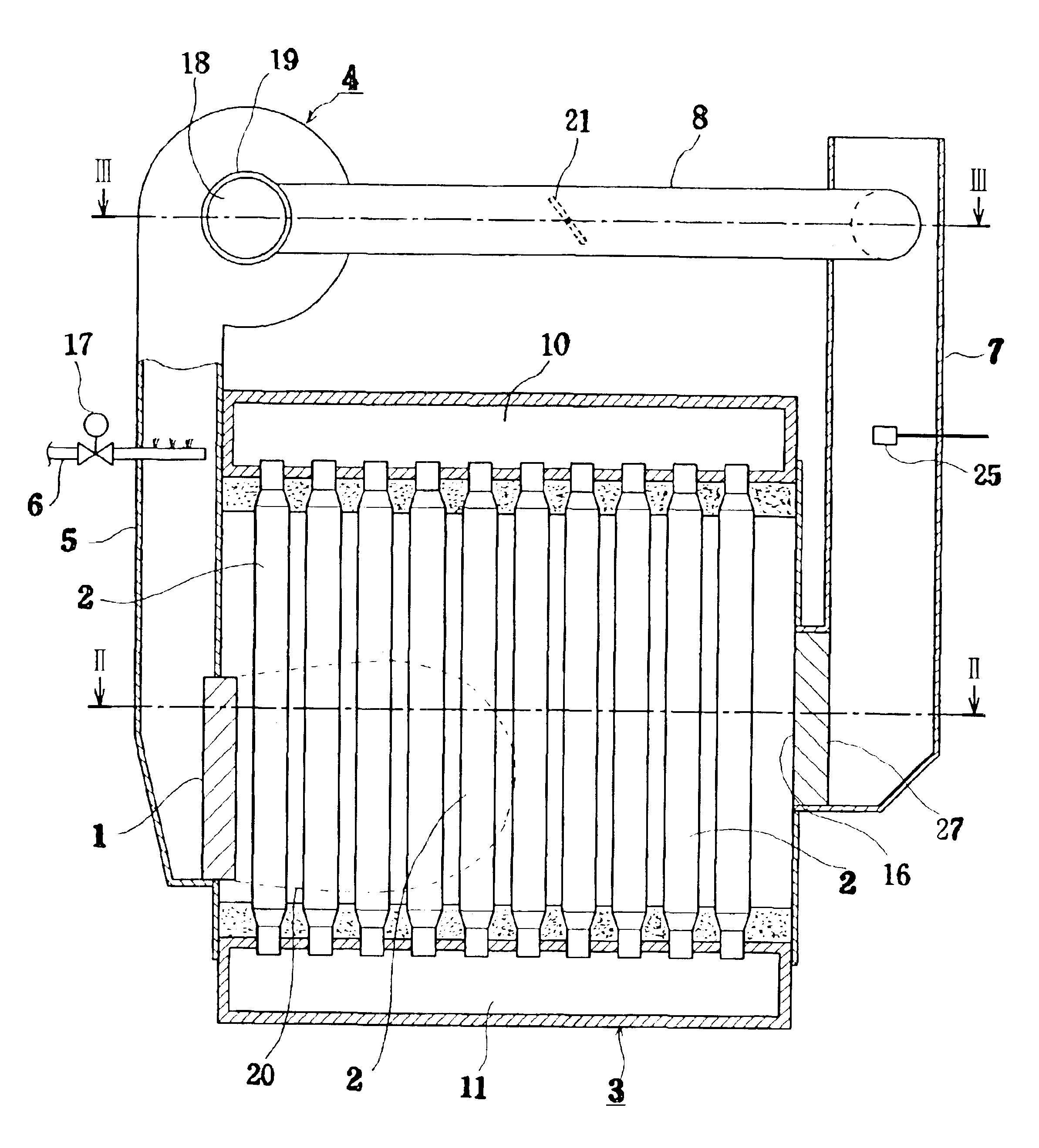
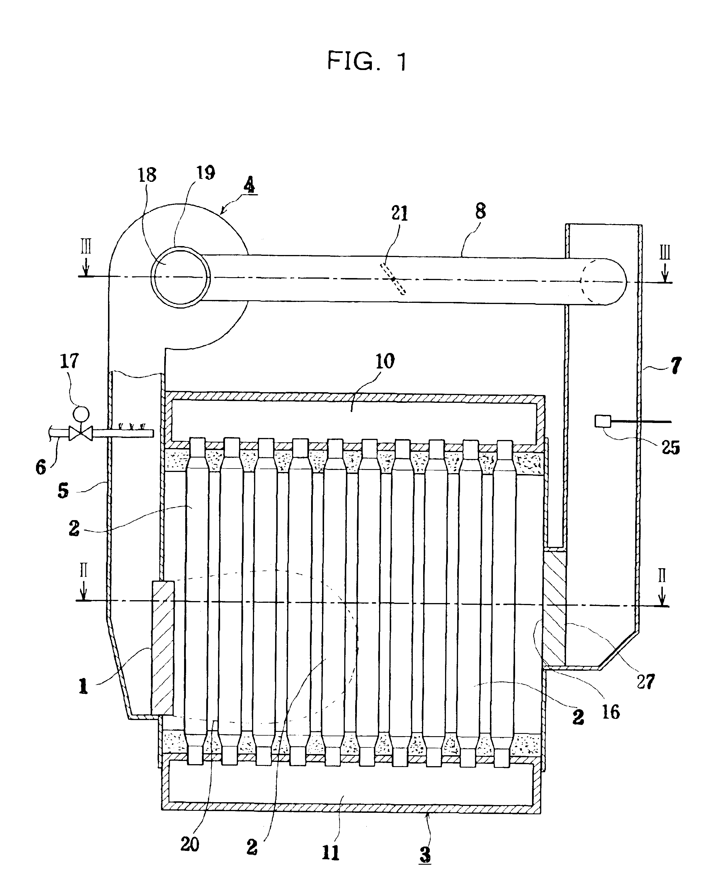
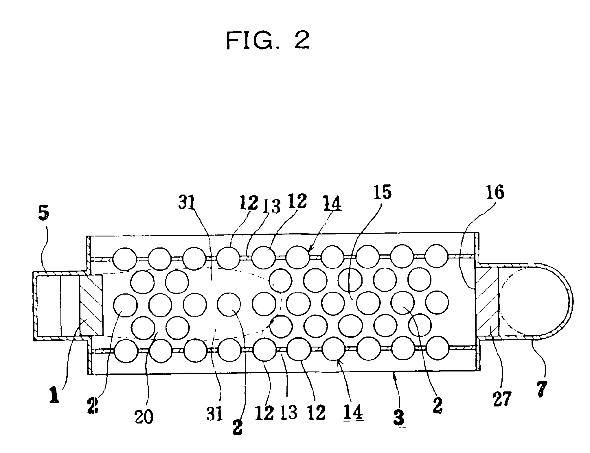
Hereinbelow, working examples in which the NOx reduction combustion method and apparatus of the present invention are applied to a once-through steam boiler, which is one type of water-tube boilers, are described in accordance with the accompanying drawings. FIG. 1 is an explanatory view of a longitudinal section of a steam boiler to which an embodiment of the present invention is applied, FIG. 2 is a sectional view taken along the line II—II of FIG. 1, FIG. 3 is a cross-sectional view taken along the line III—III of FIG. 1, FIGS. 4 and 5 are charts showing excess air ratio versus NOx characteristic as well as excess air ratio versus CO characteristic in high combustion state and low combustion state, respectively, in the same embodiment, FIG. 6 is a main-part control circuit diagram of the same embodiment, and FIG. 7 is a view showing a main-part constitution of a CO oxidation catalyst member in the same embodiment, as viewed along the direction of the exhaust gas flow.

Now the over...


PUM


Abstract

Combustion method and apparatus for NOx reduction and CO reduction which are capable of easily achieving super NOx reduction with the value of exhaust NOx under 10 ppm. The combustion method for NOx reduction by controlling the temperature of combustion gas derived from a burner includes in combination the steps of suppressing combustion gas temperature by heat absorbers; suppressing the combustion gas temperature by recirculating burning-completed gas to a combustion-gas burning reaction zone; and suppressing the combustion gas temperature by adding water or steam to combustion-use air of the burner, whereby the temperature of the combustion gas derived from the burner is suppressed.

Description

BACKGROUND OF THE INVENTIONThe present invention relates to a combustion method for NOx reduction, as well as an apparatus therefor, to be applied to water-tube boilers, reheaters of absorption refrigerators, or the like.Generally, as the principle of suppression of NOx generation, there have been known (1) suppressing the temperature of flame (combustion gas), (2) reduction of residence time of high-temperature combustion gas, and (3) lowering the oxygen partial pressure. Then, various NOx reduction techniques to which these principles are applied are available. Examples that have been proposed and developed into practical use include the two-stage combustion method, the thick and thin fuel combustion method, the exhaust gas recirculate combustion method, the water addition combustion method, the steam jet combustion method, the flame cooling combustion method with water-tube groups, and the like.With the progress of times, NOx generation sources even of relatively small capacity s...

Claims


Application Information

Patent Timeline
IPC IPC(8): F23D14/78F23D14/46F23D14/68F23D14/72F23C9/00F23C9/08F23C99/00
CPCF23C9/08F23D14/78F23D14/68F23C2202/30F23C2203/20
Inventor KAYAHARA, TOSHIHIROTAKUBO, NOBORU
Owner MIURA COMPANY LIMITED
Why Eureka
Try Eureka