Small power generating device and water faucet device

a technology of power generation device and water faucet, which is applied in the direction of electric generator control, machines/engines, mechanical equipment, etc., can solve the problems of reducing the amount of water flowing at a time, and achieve the effect of reducing the detent torqu

Inactive Publication Date: 2005-04-05
SANKYO SEIKI MFG CO LTD +1
View PDF24 Cites 54 Cited by
  • Summary
  • Abstract
  • Description
  • Claims
  • Application Information

AI Technical Summary

Benefits of technology

According to another aspect of the present invention, in addition to the aspect of the present invention described above, a detent torque generated between the stator portion and the rotor is set to be cancelled by the layers each other. For example, the detent torque is positively set to be reduced by skewing each layer (rotating the layer in a circumferential direction to intentionally shift a pole thereof) or providing a non-magnetic member between the layers. Consequently, the functions can be obtained more effectively.
Moreover, according to another aspect of the present invention, there is provided a small generator comprising a hydraulic turbine, provided in a fluid path, rotating by passing a fluid in a predetermined flow rate, a rotator, coupled to the hydraulic turbine, rotating together with the hydraulic turbine, the rotator acting as a rotor portion opposed to a stator portion having a plurality of coil portions in a brushless motor including the stator portion, wherein the rotor portion rotates relatively with respect to the stator portion by passing the fluid to generate a power. Thus, the rotator coupled to the hydraulic turbine serves as the rotor portion opposed to the stator portion of the brushless motor. Therefore, it is possible to reduce the detent torque than that in a conventional generator of a conventional single layer type stepping motor. As a result, it is possible to rotate the hydraulic turbine with a small flow at a low hydraulic pressure.
According to another aspect of the present invention, in addition to the aspect to the present invention described above, a relationship between the number of poles magnetized onto the rotor portion and the number of coil portions of the stator portion is set to 2-3, 4-3 or 4-6. Consequently, it is possible to further reduce the detent torque between the stator portion and the rotor portion.
According to another aspect of the present invention, in addition to the aspect of the present invention, there is provided an injecting member including an injecting hole which acts as a p

Problems solved by technology

Under such circumstances, there has been a problem in that the amount of water to flow a

Method used


Image

  • Small power generating device and water faucet device
  • Small power generating device and water faucet device
  • Small power generating device and water faucet device

Examples


first embodiment

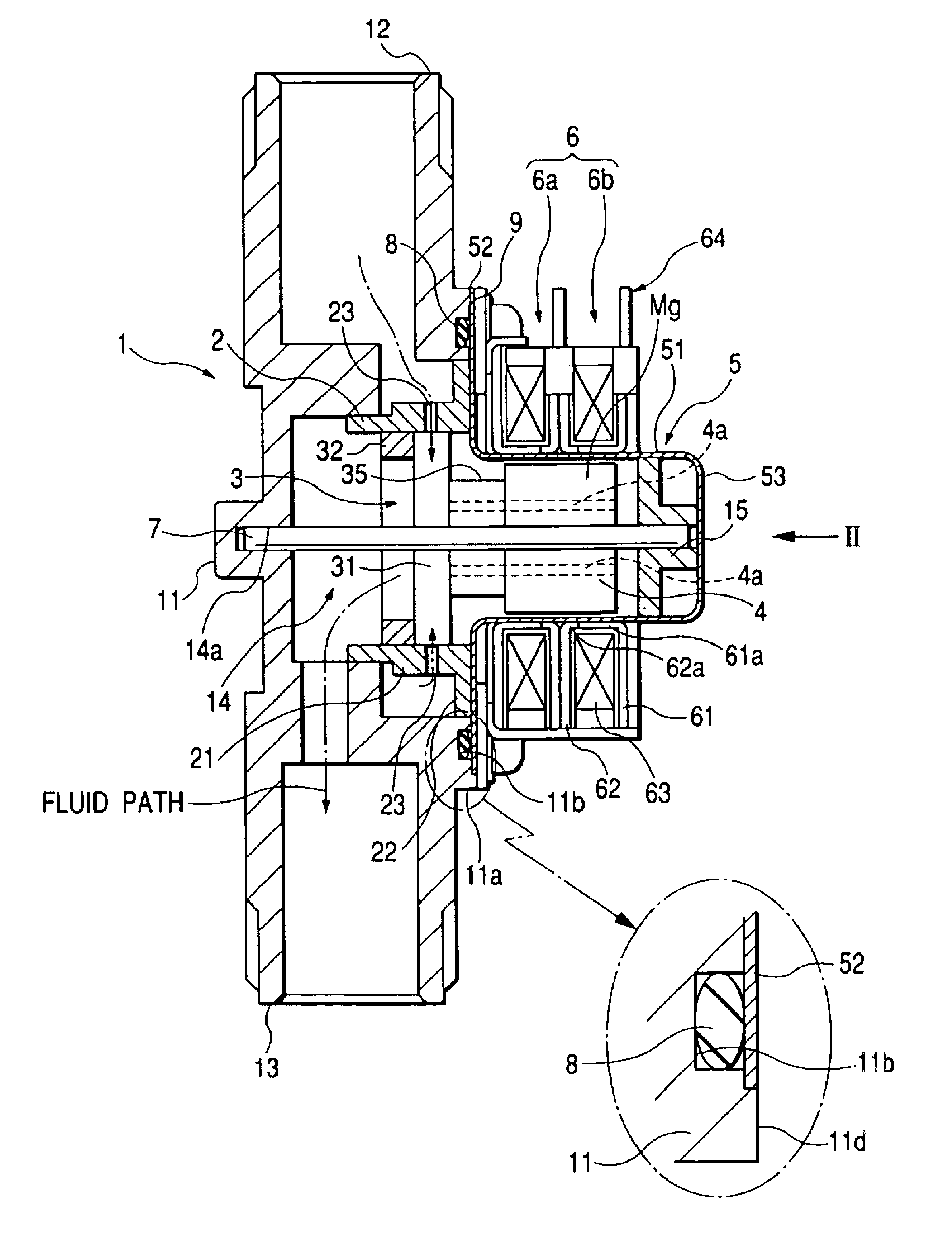
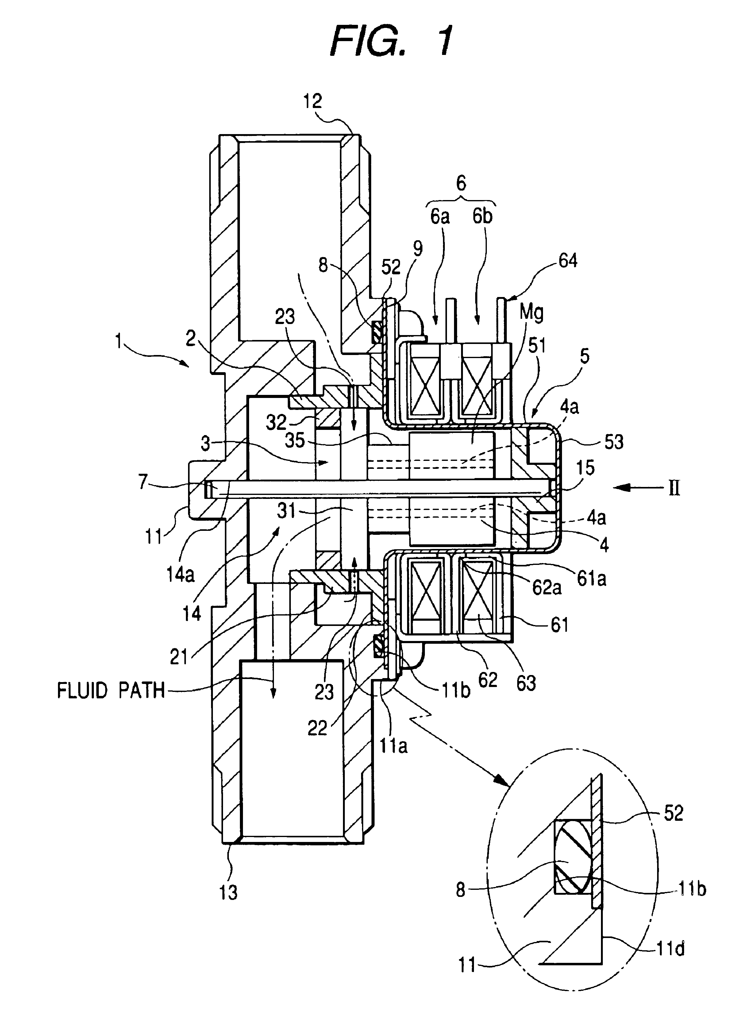
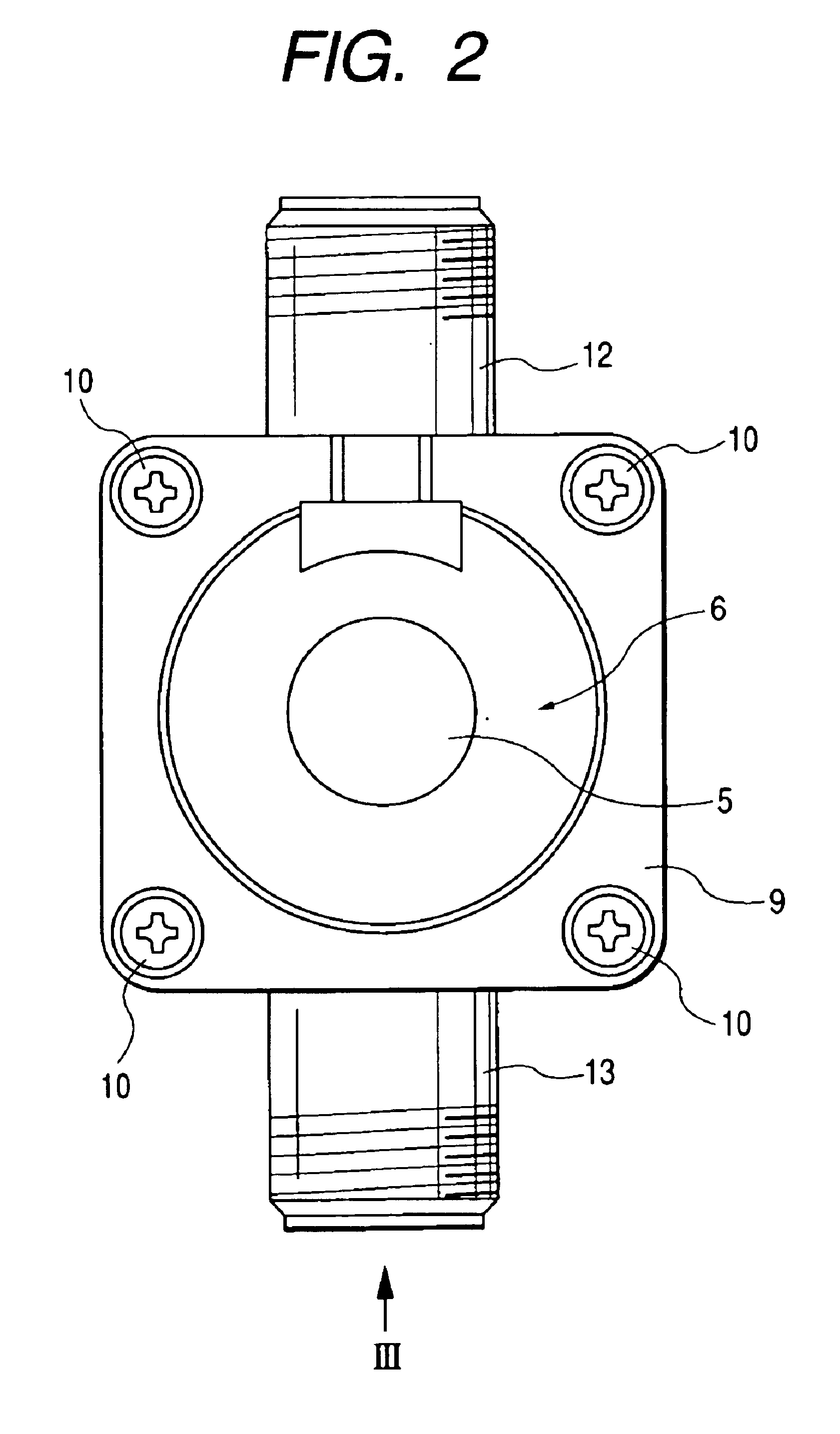
Primary, a small generator utilizing a two-layer stepping motor type according to a first embodiment of the invention will be described with reference to FIGS. 1 to 4. FIG. 1 is a longitudinal sectional view showing a small generator of a two-layer stepping motor type according to the first embodiment of the invention. Moreover, FIG. 2 is a side view showing the small generator of FIG. 1 taken along an arrow II in FIG. 1. Furthermore, FIG. 3 is a bottom view showing the state of FIG. 2 taken along an arrow III. Moreover, FIG. 4 is a typical view showing a relationship between a member (nozzle ring) for spraying a fluid onto a hydraulic turbine in a state in which a hydraulic pressure is raised by throttling a fluid path and the hydraulic turbine.

As shown in FIG. 1, the small generator utilizing a two-layer stepping motor type according to the first embodiment comprises a casing 1, a nozzle ring 2 provided in the casing 1, a hydraulic turbine 3 rotatably provided on the inner periphe...

second embodiment

Next, a small generator utilizing a brushless motor type according to a second embodiment of the invention will be described with reference to FIGS. 5 and 6. In the description of the second embodiment, the description of the same structures as those in the first embodiment will be omitted and the same components have the same reference numerals as those in the first embodiment. FIG. 5 is a longitudinal sectional view showing a small generator according to the second embodiment of the invention. Moreover, FIG. 6 is a side view showing the small generator of FIG. 5 taken along an arrow VI in FIG. 5.

As shown in FIG. 5, the small generator utilizing a brushless motor type according to the second embodiment has almost the same structure as that in the first embodiment, and includes a casing 1, a nozzle ring 2 provided in the casing 1, a hydraulic turbine 3 rotatably provided on the inner peripheral side of the nozzle ring 2, a rotor 4 rotates integrally with the hydraulic turbine 3, a c...


PUM


Abstract

A small generator includes a hydraulic turbine provided in a fluid path rotating with a passage of a fluid in a predetermined flow and a rotator coupled to the hydraulic turbine rotating together with the hydraulic turbine which acts as a rotor portion opposed to a stator portion having multiple layers in a stepping motor including the stator portion, wherein the rotor portion relatively rotates with respect to the stator portion with the passage of the fluid, thereby generating a power.

Description

BACKGROUND OF INVENTION1. Field of InventionThe present invention relates to a small generator utilizing a hydroelectric generated by a water flow passing through a faucet and a Water tap apparatus contains a small generator is provided.2. Related ArtConventionally, there is widely provided an automatic Water Tap apparatus contains a sensor sensing that a hand held out beneath a faucet. Then the faucet starts to flow water from is on the basis of the sensor sensing. In recent years, moreover, there is proposed an apparatus such that a small generator is provided in a fluid path of such an automatic Water Tap apparatus and a power generated by the small generator is storaged to complement for the power consumption of a circuit such as the sensor as shown in Japanese Utility Model Publication Hei. 2-65775.The structure of the small generator will be briefly described below. A hydraulic turbine is provided in a fluid path to be a water flowing path and rotates by receiving the hydroele...

Claims


Application Information

Patent Timeline
IPC IPC(8): F03B13/00H02K7/18H02K5/12H02K5/128
CPCF03B13/00H02K7/1823H02K5/128
Inventor YUMITA, YUKINOBU
Owner SANKYO SEIKI MFG CO LTD
Why Eureka
Try Eureka