Controlled motion system

Active Publication Date: 2005-04-05
ROCKWELL AUTOMATION
View PDF56 Cites 312 Cited by
  • Summary
  • Abstract
  • Description
  • Claims
  • Application Information

AI Technical Summary

Benefits of technology

The present invention relates to a controlled motion system, which can be employed in a manufacturing or other type of machine to control the movement and operation of a tool, payload, or other items that need to be moved to effect a process. A preferred embodiment of the system includes a track and a mover that is mounted movably on the track for moving along a path. Active and reactive elements are associated with the track and mover and configured for driving and controlling the position of the mover along the path. A controller is operably associated with the active elements for controlling the driving of the mover. A position sensor is associated with the track and configured for sensing the position information, which corresponds to the position of the mover along the path. The position information is preferably true absolute position

Problems solved by technology

This results in lost production time and, oftentimes, lost product.
Traditional linear motors suffer from a variety of limitations.
This configuration can limit the number of movable elements and the length of the track since the mechanical complexity and electrical reliability of the system becomes impractical with a large number of sensor and switch tracks and elements.
Additionally, the position sensing system disclosed is an incremental type, with the limitations desc

Method used


Image

  • Controlled motion system
  • Controlled motion system
  • Controlled motion system

Examples


Embodiment Construction

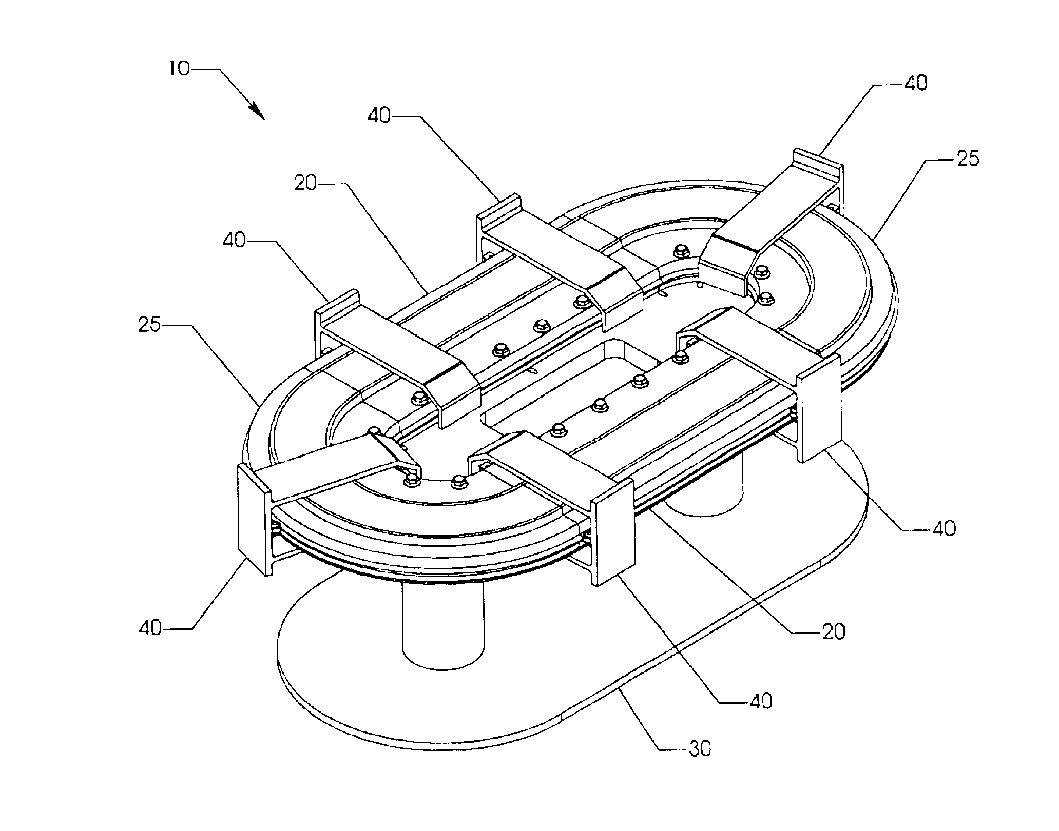
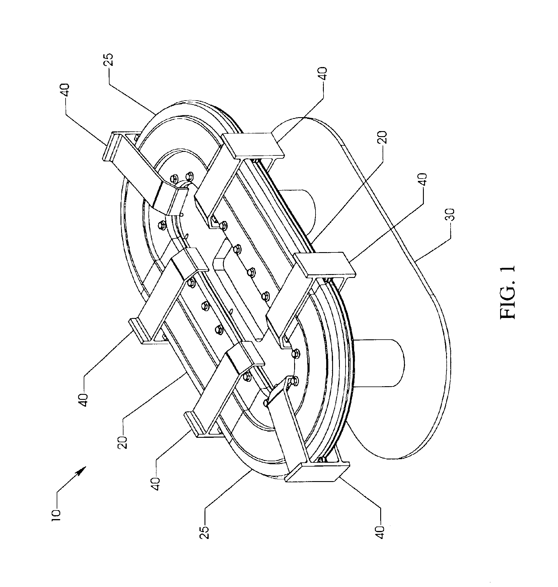
In the embodiment of FIG. 1, a closed-path track assembly has a track 10 and at least one moving element, which is preferably a mover 40, mounted on linear-motor stator modules, which preferably include two straight linear motor stator modules 20 and two constant-radius curved linear motor stator modules 25. Each mover 40 is preferably movable independent of all of the other movers 40. All four linear motor modules 20, 25 are mounted to a common frame 30. In the preferred embodiment, track 10 and movers 40 cooperatively function as a motion control system for independently controlling the motion of each mover 40 along the path.

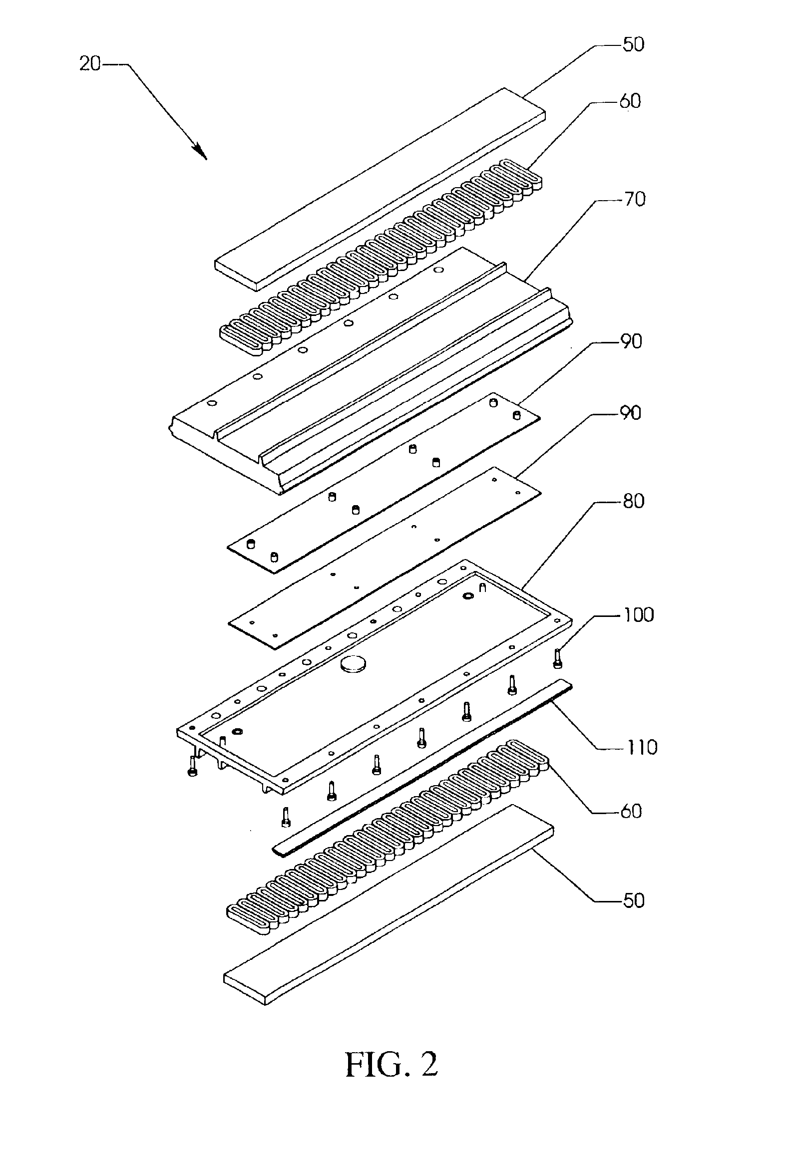
As shown in FIGS. 2 and 3, linear motor modules 20 and 25 include preferably active elements 60 sandwiched between encapsulation 50 and stator top plate 70 or stator bottom plate 80, respectively. Controllers 90 are mounted to the stator plates 70, 80, and fasteners 100, preferably fasten the assembly together, a control parameter sensor 110 is preferably moun...


PUM

PropertyMeasurementUnit
Speedaaaaaaaaaa
Speedaaaaaaaaaa
Timeaaaaaaaaaa

Abstract

A controlled motion system, which has a mover that is movably mounted on a track for moving along a path. Active and reactive elements are associated with the track and mover, and are configured for driving and controlling the mover along the path. A controller is operatively associated with the active elements for controlling the driving of the mover, and a position sensor is associated with the track and configured for sensing the position information corresponding to the position of the mover along the path. The sensor is associated with the controller for transmitting the position information to the controller. The sensors are also preferably configured such that the position information is transmitted from the mover through the sensor at a sensing speed faster than about 10,000 meters per second. The controller is preferably configured for controlling the active element depending on at least one parameter related to the movement of the mover such that at least one mover is controlled independently from the others.

Description

BACKGROUND OF INVENTIONThe present invention relates to motion control systems and, more specifically, to linear motor systems that provide independent control of multiple moving elements.The application of such devices to a wide variety of processes (e.g. packaging, assembly automation, processes involving use of machine tools, etc.) provides the advantage of increasing both the speed and flexibility of the process. Since linear motors employ a moving magnetic field to directly drive the moving element, they eliminate the gear heads, shafts, keys, sprockets, chains and belts often used with traditional rotary motors. This reduction of mechanical complexity provides both reduced cost and increased speed capability by virtue of reduced inertia, compliance, damping, friction and wear. This technology also provides greater flexibility than rotary motors by allowing each individual moving element and its associated tool or payload to be independently servocontrolled along its entire pat...

Claims


Application Information

Patent Timeline
IPC IPC(8): H02K41/03
CPCB60L15/38B29C65/02B65B35/52B65G47/5104B65G47/841B65G54/02H02K11/0015H02K41/031B29C66/1122B29C66/131B29C66/4312B29C66/4322B29C66/82263B29C66/83523B29C66/849B65B9/20B65B35/10B65B51/306B65B65/02Y02T10/641B65B9/06B29C65/7867B29C66/81465B29C66/8244B29C66/83413B29C66/8351G01D5/145H02K11/215Y02T10/64
Inventor JACOBS, KEITH
Owner ROCKWELL AUTOMATION
Why Eureka
Try Eureka