Optical recording method and optical recording device

a recording method and recording magnetic field technology, applied in the field of optical recording methods and optical recording devices, can solve the problems of difficult to achieve high density recording, affecting the quality of recording, so as to improve the level of high density track recording

Inactive Publication Date: 2005-04-05
SHARP KK
View PDF12 Cites 12 Cited by
  • Summary
  • Abstract
  • Description
  • Claims
  • Application Information

AI Technical Summary

Benefits of technology

[0010]The present invention addresses the aforementioned problem and has an objective to offer an optical recording method and device which, even if recording sensitivity differs between adjacent tracks, is capable of controlling the width of the recording mark to be optimum, minimizing cr

Problems solved by technology

One of obstacles in doing so is that when a recording condition, such as the quantity of a recording light beam projected on the optical disk or the strength of a recording magnetic field externally applied on the magneto-optical disk, changes, the resultant recording marks vary in width (a size measured perpendicular to the track), which obstructs uniform recording and makes it difficult to effect high density recording.
Therefore, if r

Method used


Image

  • Optical recording method and optical recording device
  • Optical recording method and optical recording device
  • Optical recording method and optical recording device

Examples


embodiment 1

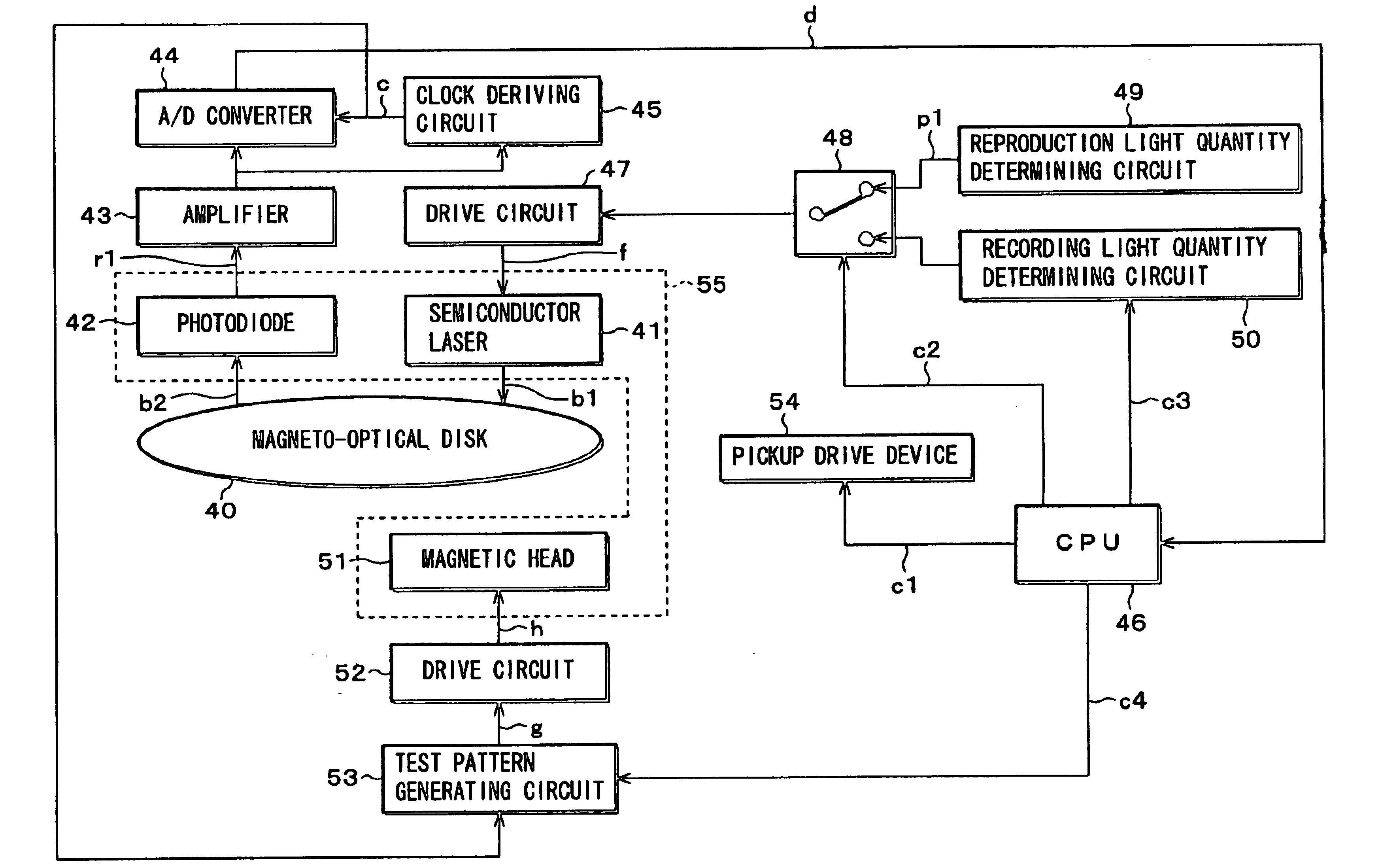
[0067]Taking magneto-optical recording methods and devices as examples, the following description will discuss an embodiment of the present invention in reference to FIG. 1(a) to FIG. 1(d), FIG. 2, and FIG. 3.

[0068]Here, magneto-optical recording is effected through modulation of a magnetic field. There are various recording conditions that should be optimized in magnetic-field-modulated recording: namely, the quantity of recording light (the quantity of a light beam projected on the optical recording medium during recording), the strength of a recording magnetic field (the strength of a magnetic field applied to the optical recording medium during recording), etc. Among them, we will focus for convenience in description on the quantity of recording light As to optimization of the strength of a recording magnetic field, a similar description applies, so a brief explanation will be given at the end. Accordingly, hereinafter, the strength of a recording magnetic field is assumed to be...

embodiment 2

[0096]Now the following description will discuss another embodiment of the present invention in reference to FIG. 4 and FIG. 5. Here, for convenience, the members of the present embodiment that are identical to those of embodiment 1 will not be explained in detail, or their description will be totally omitted.

[0097]According to embodiment 1, changes were detected in the amplitudes of signals reproduced from the track Tr(n) and its adjacent track Tr(n+1) to determine an optimum quantity of light In some cases, however, this method fails and it becomes impossible to determine an optimum quantity of light

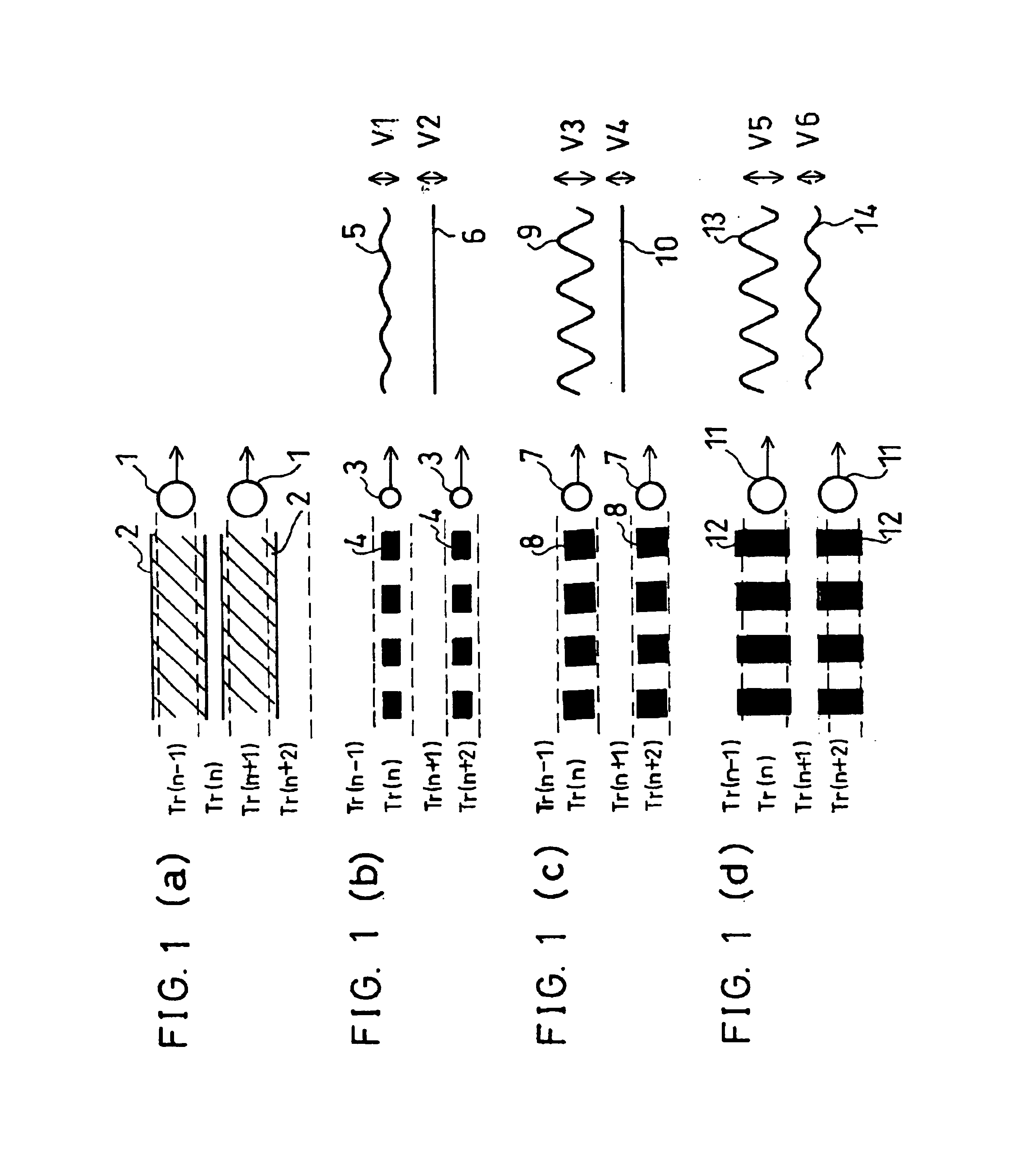
[0098]FIG. 4 is drawn by plotting the amplitudes V(n) and V(n+1) of the read-out signals reproduced respectively from the track Tr(n) and its adjacent track Tr(n+1) against the quantities of recording light, with recording marks being written in the tracks Tr(n) and Tr(n+2) under a recording condition illustrated in FIG. 1(b) (condition (b)), that illustrated in FIG. 1(c) (condition (c...

embodiment 3

[0112]The following description will discuss another embodiment of the present invention in reference to FIGS. 2, 6(a) to 6(d), 7, 8, 9, 10(a) to 10(c), 11, 12, and 13. Here, for convenience, the members of the present embodiment that are identical to those of the previous embodiments will not be explained in detail, or their description will be totally omitted.

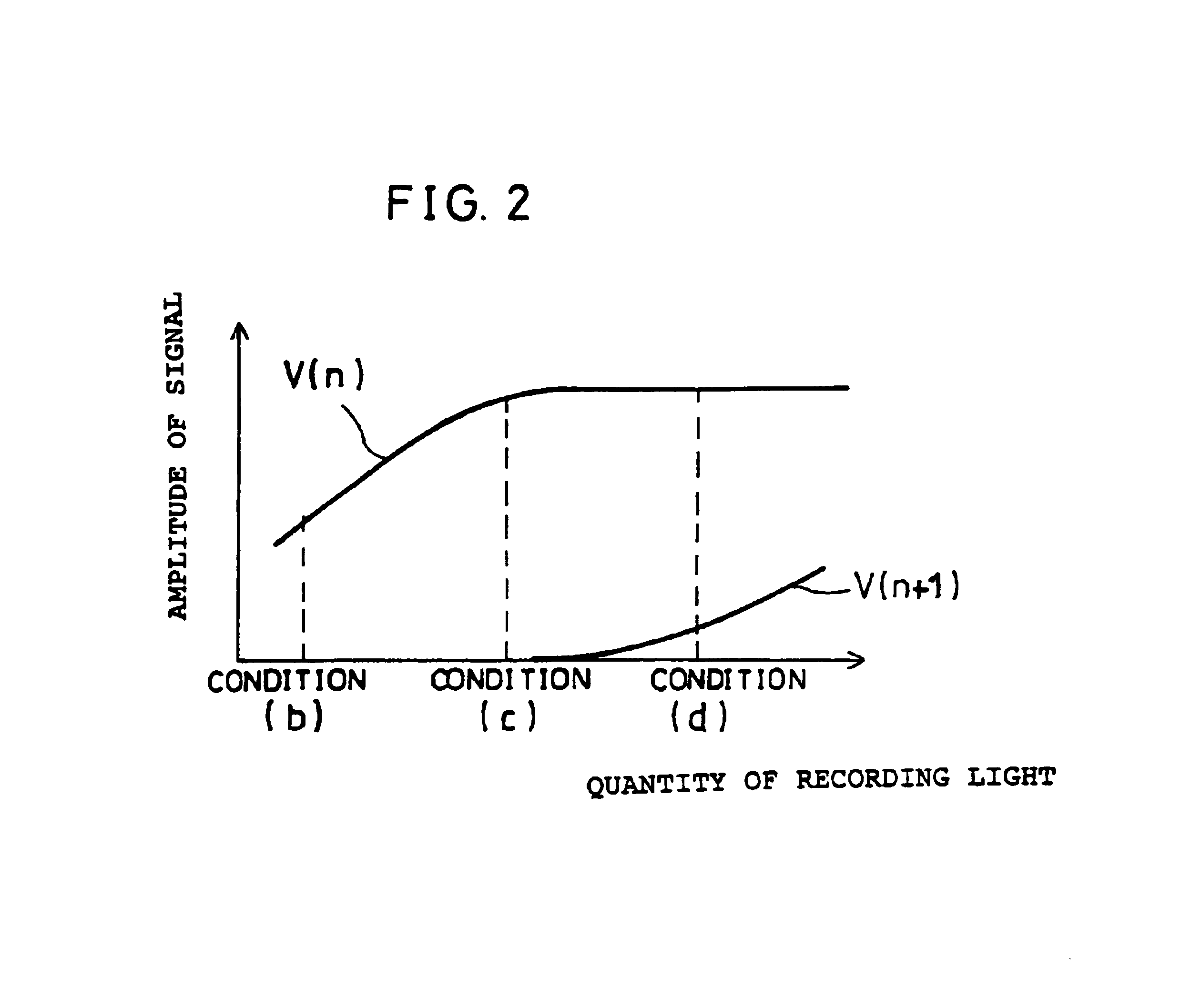
[0113]Those methods detailed in embodiments 1 and 2 were such that the width of recording marks was readily controllable based on variations in the amplitude of a signal reproduced from a specified track and those of a signal reproduced from an adjacent track which is affected by spillover effects. However, the detecting sensitivity is not sufficiently high, because the amplitude V(n+1) of a signal reproduced from the track Tr(n+1) is small as shown in FIG. 2.

[0114]Accordingly, in the present embodiment, a method will be discussed whereby the amplitude varies greatly so that the optimum quantity of recording light is detectab...


PUM


Abstract

A reverse pattern is formed in a track adjacent to a specified track on an optical recording medium with a predetermined light beam capable of writing large recording marks. Thereafter, a normal pattern is formed in an area, of an adjacent track, which is adjacent to the reverse pattern in the specified track with recording light beams of various strengths, the adjacent track being adjacent to the specified track. The specified track is read to detect a plurality of re-out signals according to individual light beam conditions. The adjacent track is read to detect a plurality of read-out signals according to individual light beam conditions. An optimum recording condition is determined for the specified track from the plurality of light beam condition and the read-out signals from the specified track and the adjacent track, and information is recorded in the specified track according to the optimum recording condition. Thus, even when there exists a difference in recording sensitivity between adjacent tracks, since the width of the recording marks can be controlled to be optimum, cross-talk between tracks during signal reproduction and cross-erase during signal recording are restrained to minimum levels, and recording density is improved.

Description

FIELD OF THE INVENTION[0002]The present invention relates to optical recording methods and optical recording devices to record information on optical recording media, in particular, to optical recording methods and optical recording devices capable of optimizing a recording condition.BACKGROUND OF THE INVENTION[0003]In recent years, researches have been conducted with increasing vigor to achieve an improved level of high density recording with optical disks. One of obstacles in doing so is that when a recording condition, such as the quantity of a recording light beam projected on the optical disk or the strength of a recording magnetic field externally applied on the magneto-optical disk, changes, the resultant recording marks vary in width (a size measured perpendicular to the track), which obstructs uniform recording and makes it difficult to effect high density recording.[0004]A solution to this problem is disclosed in Japanese Laid-Open Patent Application No. 11-73700 / 1999 (Tok...

Claims


Application Information

Patent Timeline
IPC IPC(8): G11B7/125G11B7/0045G11B7/00G11B5/09G11B7/0055G11B7/007G11B7/1267
CPCG11B7/1267G11B7/00718G11B11/10595G11B11/1053G11B7/0045
Inventor ADACHI, YOSHIHISA
Owner SHARP KK
Why Eureka
Try Eureka