Switching system

a technology of switching system and switch, applied in the field of data switching devices and apparatuses, can solve the problems of insufficient processing technology to meet all of this demand, costing the overall performance of either option, and the general inability to meet the demand of the user,

Inactive Publication Date: 2005-04-05
MICRON TECH INC
View PDF11 Cites 35 Cited by
  • Summary
  • Abstract
  • Description
  • Claims
  • Application Information

AI Technical Summary

Problems solved by technology

Unfortunately, improvements in processor technology, though impressive, are insufficient to satisfy all of this demand.
Thus, either the node must suspend processing, or (where possible) it must switch to another task which is not so stalled—either option will cost overall performance.
By contrast, cell loss in processor interconnect systems is generally unacceptable due to the stalled requesting process, yet such systems typically operate with a minimum of protocol layers in order to keep down system latency.

Method used


Image

  • Switching system
  • Switching system
  • Switching system

Examples


Embodiment Construction

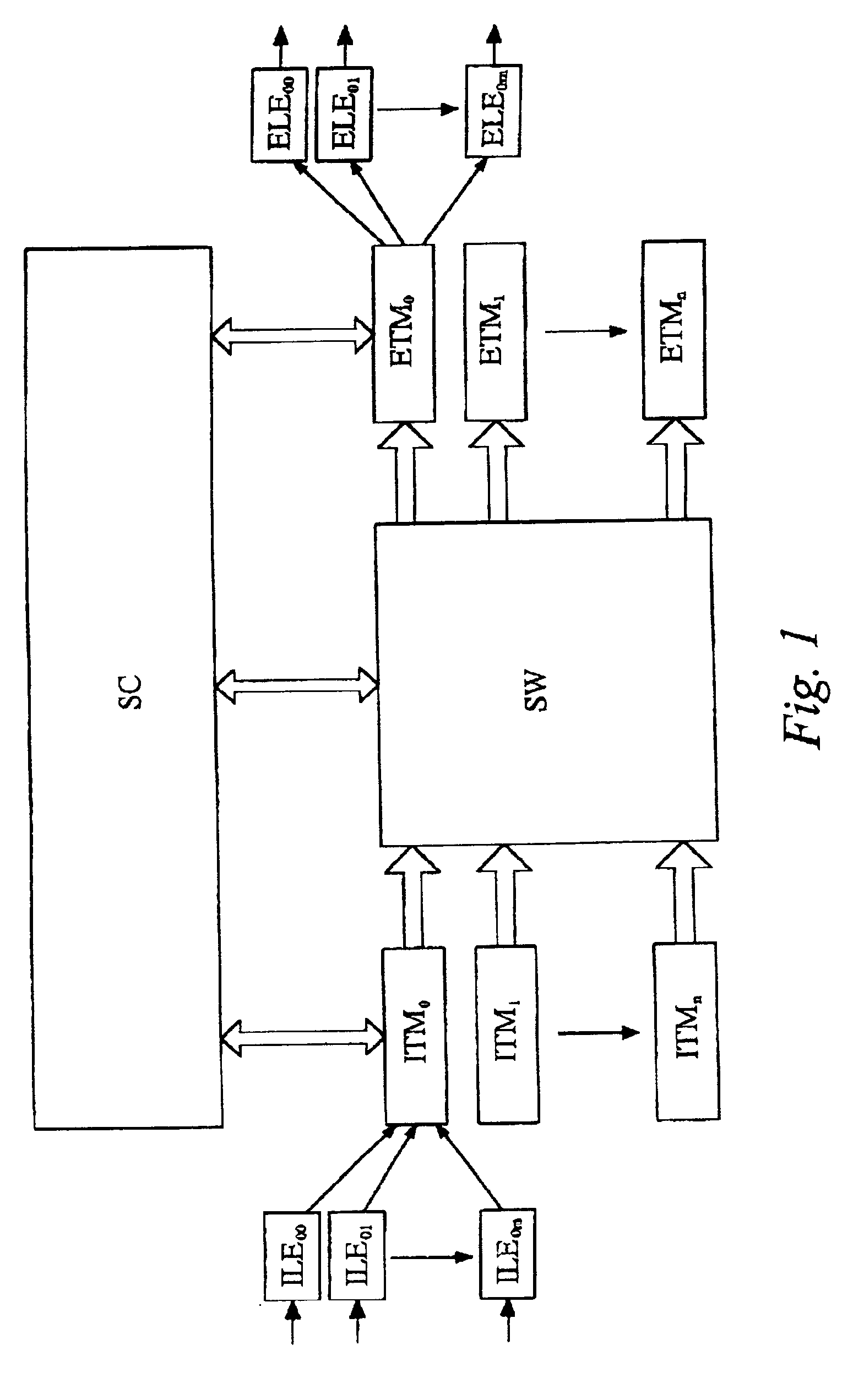
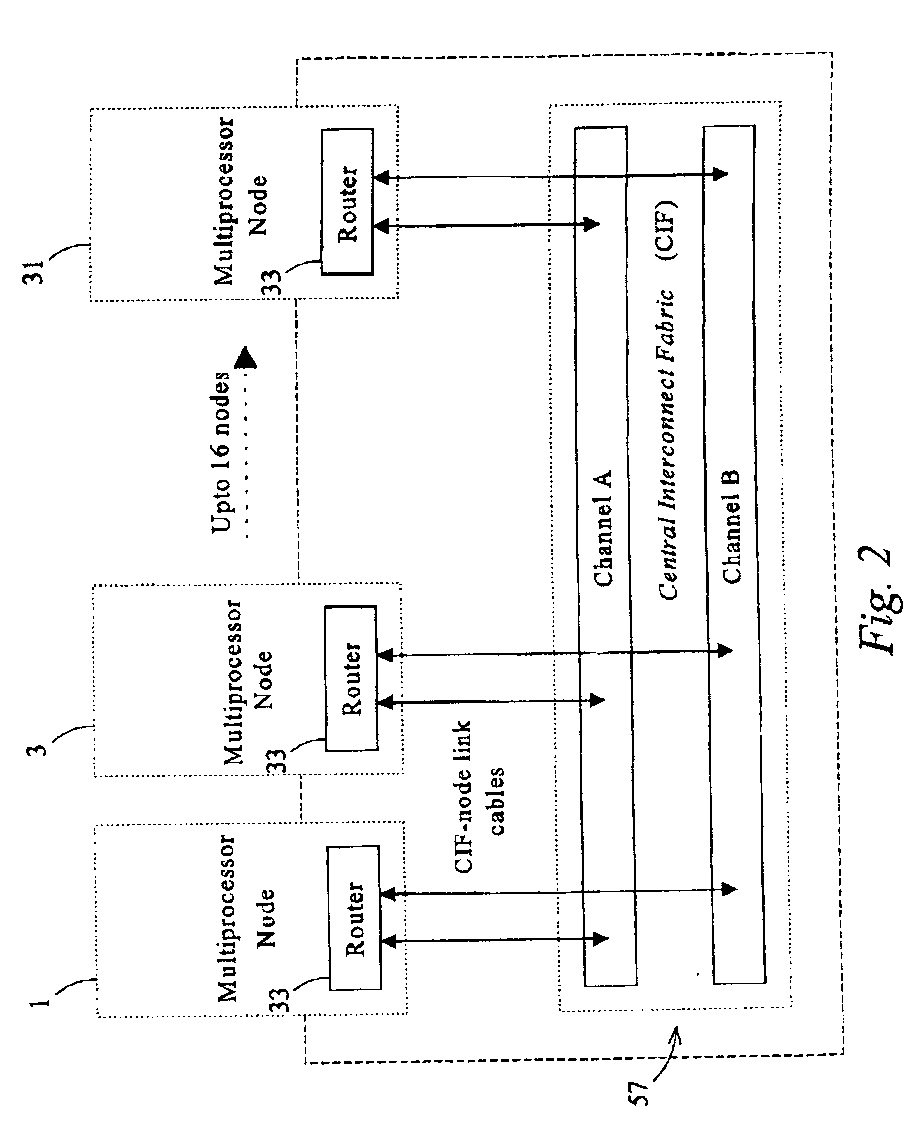
The embodiment of the present invention described herein is a development of the system described above with reference to FIG. 1, with further reductions to the latency and improvements in fault tolerance. The embodiment is illustrated in FIG. 2, which shows a system having a number (up to 16) of multi-processor nodes 1, 3, . . . 31. Each node contains a router device 33. The router devices provide the interface (both receiving and transmitting information) between each processing node and a central interconnect fabric 57.

The fabric 57 is organised as two independent channels with separate power and clock domains. Each channel consists of a single master and several matrix devices, with the number of matrix devices determining the aggregate bandwidth of the fabric. The router of each node of the multiprocessor system connects into the fabric through an array of high-speed serial links operating over cables. As in the known system described above in relation to FIG. 1, the present em...


PUM


Abstract

A data switching device has ingress routers and egress routers interconnected by a switching matrix controlled by a controller. Each ingress router maintains one or more virtual output queues for each egress router. The switching matrix itself maintains a head-of queue buffer of cells which are to be transmitted. Each of these queues corresponds to one of the virtual output queues, and the cells stored in the switching matrix are replicated from the cells queuing in the respective virtual output queues. Thus, when it is determined that a connection is to be made between a given input and output of the switching matrix, a cell suitable for transmission along that connection is already available to the switching matrix. Upon receipt of a new cell by one of the ingress routers, the cell is stored in one of the virtual output queues of the ingress router corresponding to the egress router for the cell, and also written the corresponding head of queue buffer, if that buffer has space. If not, the cell is stored, and written to the head of queue buffer when that buffer has space for it.

Description

FIELD OF THE INVENTIONThe present invention relates to devices and apparatus for data switching One example of the use of the present invention is to provide high bandwidth interconnection within systems in which two or more processors share memory.BACKGROUND OF THE INVENTIONThe ever-expanding requirements for processing-intensive computer applications are driving the market to produce systems of ever-greater power. Unfortunately, improvements in processor technology, though impressive, are insufficient to satisfy all of this demand.One alternative possibility for creating a system with increased power is to operate several closely coupled processing nodes in tandem. Though each node operates in its own local memory space, the close coupling necessitates a degree of memory sharing. This shared memory can be implemented as a single central copy, or (more typically) replicated and distributed in the nodes' local memory. Either way this gives rise to the need for a high bandwidth inter...

Claims


Application Information

Patent Timeline
Patent Type & Authority Patents(United States)
IPC IPC(8): H04L12/56H04Q3/545H04Q11/04H04L49/111
CPCH04L49/254H04Q3/5455H04Q11/0478H04L49/101H04L49/30H04L49/3027H04L49/3045H04Q2213/13196H04Q2213/1302H04Q2213/1304H04Q2213/131H04Q2213/13103H04Q2213/13106H04L12/28
Inventor JOHNSON, IAN DAVIDDUXBURY, COLIN MARTINPIEKARSKL, MAREK STEPHEN
Owner MICRON TECH INC
Why Eureka
Try Eureka