Unit designing apparatus and method

a design apparatus and design method technology, applied in the direction of total factory control, programme control, electric programme control, etc., can solve the problems of not holding systematic discussions between the design team and the production engineering team, difficult to include or reflect in a new design the matters concerning production techniques performed for past design examples, etc., to achieve the effect of competitiveness in the mark

Inactive Publication Date: 2005-04-05
TOYOTA JIDOSHA KK
View PDF10 Cites 35 Cited by
  • Summary
  • Abstract
  • Description
  • Claims
  • Application Information

AI Technical Summary

Benefits of technology

An object of the present invention is to reflect, in design of a new unit including a plurality of function blocks, the accumulated results of past design examples for which consultations concerning production techniques were performed, thereby eliminating repetition of designs and reducing time required for development. Further objects are to allow consultation regarding aspects concerning production techniques before determining the basic shape of the unit, to allow sufficient evaluations of mountability, assembly, strength, and the like to be conducted at an earlier stage, and to allow an engine design team and a production engineering team to simultaneously participate in design. Another object of the present invention is to accumulate the results of the new design as an additional design example, so as to further enhance the level of unit design standardization.
According to the unit designing apparatus of the present invention, a design example including an outer shape of each of the function blocks may be stored in association with a specification including a basic dimension of the unit. In this database, a design example that can be applied is searched for each of the plurality of function blocks using a specification of the unit as the key. An outer shape for each of the function blocks obtained as a result of the search is then laid out in a basic structural view of the unit to thereby design a raw material shape for the unit. In this manner, the accumulated results of past design examples for which consultations concerning production techniques were performed can be reflected in forming new designs, thereby preventing the recreation of designs and thereby reducing the time required for development. Further, as additional examples can be subsequently stored, the level of unit design standardization can be further enhanced.
Further, in the unit designing apparatus of the present invention, production machining information including a machining shape applied to each function block is stored. In such a database, production machining information including a machining shape for application to each of the function blocks in its raw material shape is searched. A machining shape for each of the function blocks obtained as a result of the search is then applied to the raw material shape for the unit to thereby design a product shape for the unit. The machining shape referred to herein may include a shape into which a material is processed by machining or the like. In this manner, the accumulated results of past design examples for which consultations concerning production techniques were performed can be reflected in forming new designs, thereby preventing repetitive designs and thereby reducing time the required for development. As the basic shape of the unit is not decided until the machining shape is applied, consultation regarding aspects of production techniques can be accomplished before the decision, allowing sufficient evaluations of mountability, assembly, strength, and the like to be conducted at an earlier stage and while allowing the design team and the production engineering team to simultaneously participate in design. Moreover, the results of a new design can be accumulated as an additional design example, thereby further enhancing the level of unit design standardization.
When developing a unit, it is necessary to continually incorporate new technologies to create products that effectively compete in the market. According to the configuration described above, a new function block incorporating such new technologies can be designed by referring to or consulting design examples already stored in the function block database, and the designed function block can be newly registered in the function block database. Similarly, new production machining information for application to the newly designed function block can be created by referring to or consulting the production machining data already stored in the production machining information database, and the created machining information can be newly registered in the production machining information database. In this manner, designing of a unit raw material shape incorporating new technologies can be accomplished, and creation of a unit product shape incorporating new technologies can also be achieved.

Problems solved by technology

However, as it is still difficult at this stage to fully present the whole aspect of the engine to those other than the members of the design team, no systematic discussions are held between the design team and the production engineering team.
For this reason, it is often difficult to include or reflect in a new design the matters concerning production techniques performed for past design examples.
Furthermore, as accommodations to matters concerning the production techniques are made in later stages of the designing procedure, the accommodations can often only be included with great difficulty.
Similarly, as mountability, assembly, strength, and the like are not evaluated until a later stage, it is also often difficult to incorporate design modifications determined as necessary after that evaluation.
As such, the conventional design process is problematic in that significant portions of the designs must be redone, increasing the workload and prolonging the time required for development.

Method used


Image

  • Unit designing apparatus and method
  • Unit designing apparatus and method
  • Unit designing apparatus and method

Examples


Embodiment Construction

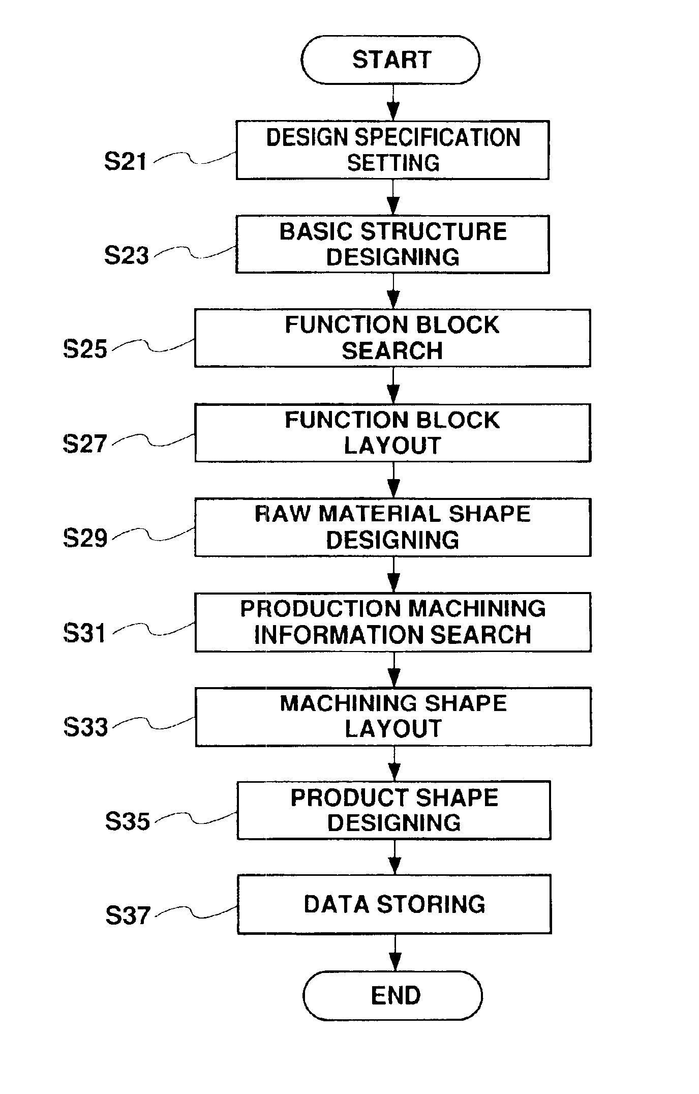
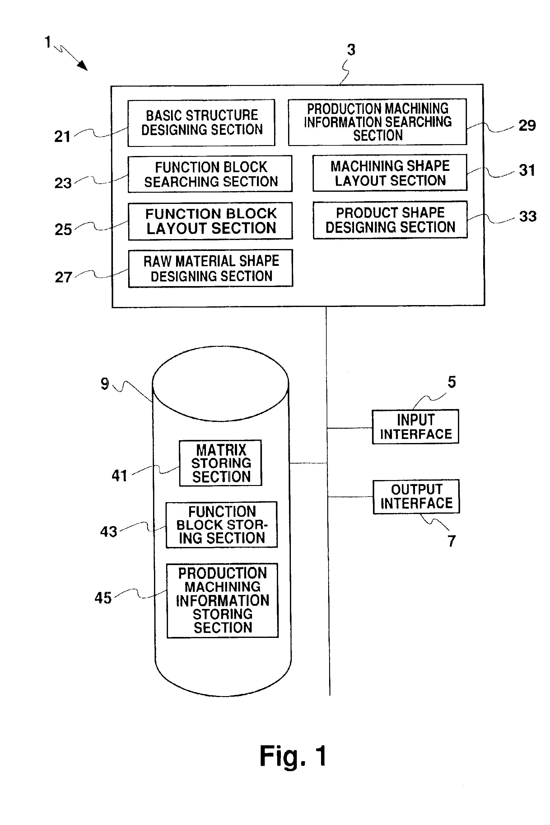
An embodiment of the present invention will next be described in detail while referring to the drawings. Although a vehicle engine will be described as an example of a unit including a plurality of function blocks, the present invention may be appropriately applied to other units. FIG. 1 is a block diagram showing the unit designing apparatus 1 which is a typical computer. The unit designing apparatus 1 comprises a CPU 3, an input interface 5, an output interface 7, and an external memory device 9, all of which are connected via a bus. The unit designing apparatus 1 may connect to an externally provided database through a network connection via the input interface 5 and the output interface 7.

The CPU 3 includes a basic structure designing section 21 for designing a basic structure in accordance with a given design target, and a function block searching section 23 for searching a design example of a function block for application to the engine concerned. The function block layout sec...


PUM


Abstract

Unit design according to the present invention makes it possible for accumulated results of past design examples to be reflected in forming new designs, thereby preventing repetitive of designs and thereby reducing the time required for development. In the unit designing apparatus (1), the CPU (3) includes a basic structure designing section (21) for designing a basic structure in accordance with a given design target, and a function block searching section (23) for searching a design example of a function block for application to the engine concerned. The function block layout section (25) lays out a retrieved outer shape of a function block in a basic structural view to design a raw material shape. The CPU (3) further includes a production machining information searching section (29) for searching production machining information for application to each function block. The machining shape layout section (31) lays out a machining shape of each function block obtained from the searched production machining information in a raw material shape design drawing to design the product shape.

Description

FIELD OF THE INVENTIONThe present invention relates to unit designing apparatus and method for designing a unit including a plurality of function blocks.BACKGROUND OF THE INVENTIONWhen designing a unit including a plurality of function blocks, such as an engine of a vehicle, it is necessary to consider not only matters concerning the engine performance but also mountability and assembly of the engine onto the vehicle, factors such as performance and strength of the function blocks, and aspects related to productivity, such as the production facilities and the man-hours required for production. It is therefore important that in an automobile manufacturer designs be planned not just by an engine design team alone, but in cooperation with a production engineering team in charge of production and processing techniques for each of the function blocks. Conventionally, after determining a target for an engine design, the design team first designs the basic shape of the overall engine. Cons...

Claims


Application Information

Patent Timeline
Patent Type & Authority Patents(United States)
IPC IPC(8): G05B19/418G06F17/50
CPCG05B19/41885Y02P90/02
Inventor TAKEDA, NOBUHIROKETA, MICHIYOSHIOKUSA, KAZUHIKO
Owner TOYOTA JIDOSHA KK
Why Eureka
Try Eureka