

Electric power steering system
- Summary
- Abstract
- Description
- Claims
- Application Information
AI Technical Summary
Benefits of technology
Problems solved by technology
Method used
Image

Examples
embodiment 1
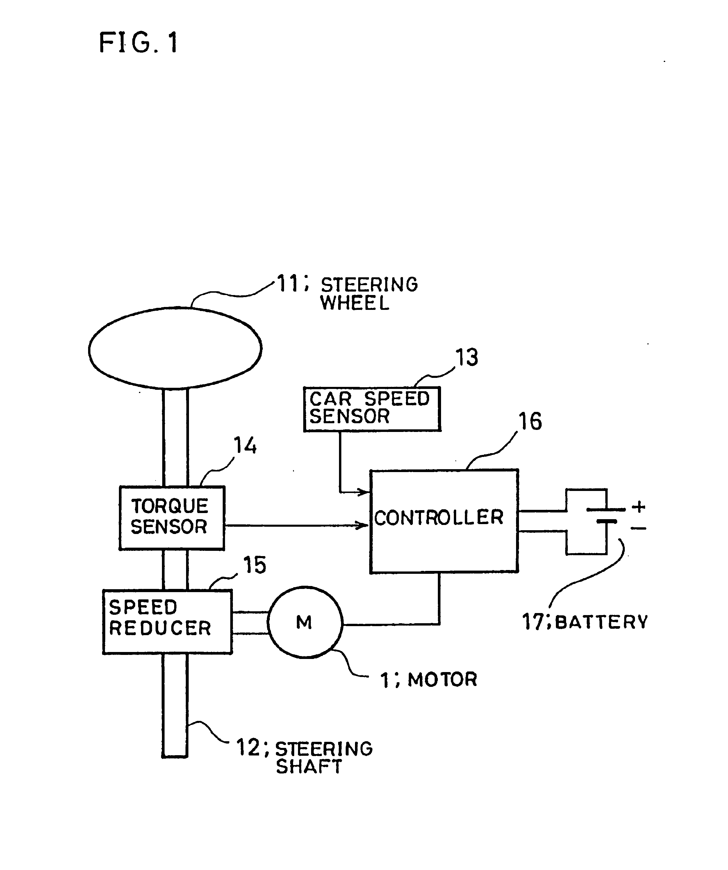
FIG. 1 is a diagram showing the whole constitution of an electric power steering system according to Embodiment 1 of the present invention. In FIG. 1, reference numeral 1 denotes a motor connected to a steering system, 11 a steering wheel, 12 a steering shaft connected to the steering wheel 11, 13 a car speed sensor for detecting the speed of an automobile by detecting the rotation of an unshown transmission, 14 a torque sensor, connected to the steering shaft, for detecting the steering torque of a driver, 15 a motor reduction gear (to be referred to as “reduction gear” hereinafter) for transmitting the output torque of the motor 1 to the steering shaft 12, 16 a controller for driving and controlling the motor 1 based on signals from the car speed sensor 13, the torque sensor 14 and the like, and 17 a battery as a power source for the controller 16.
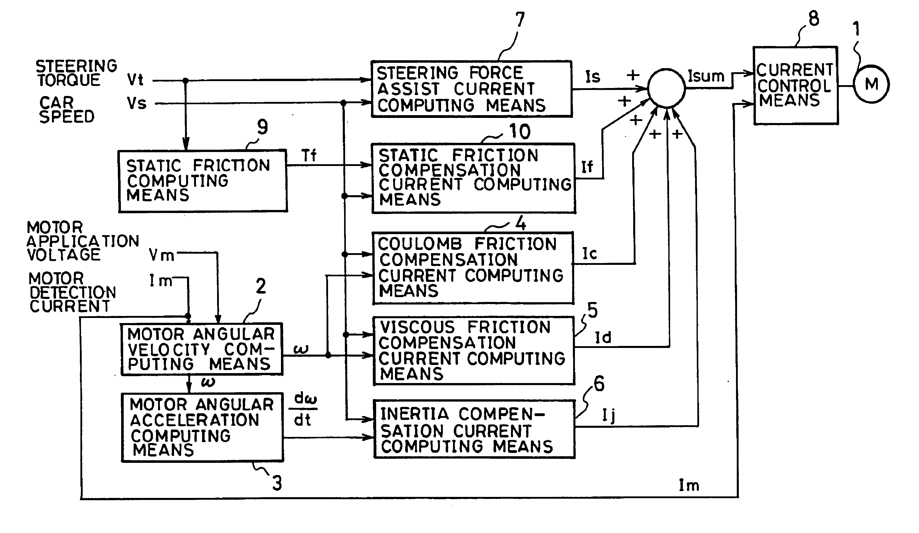
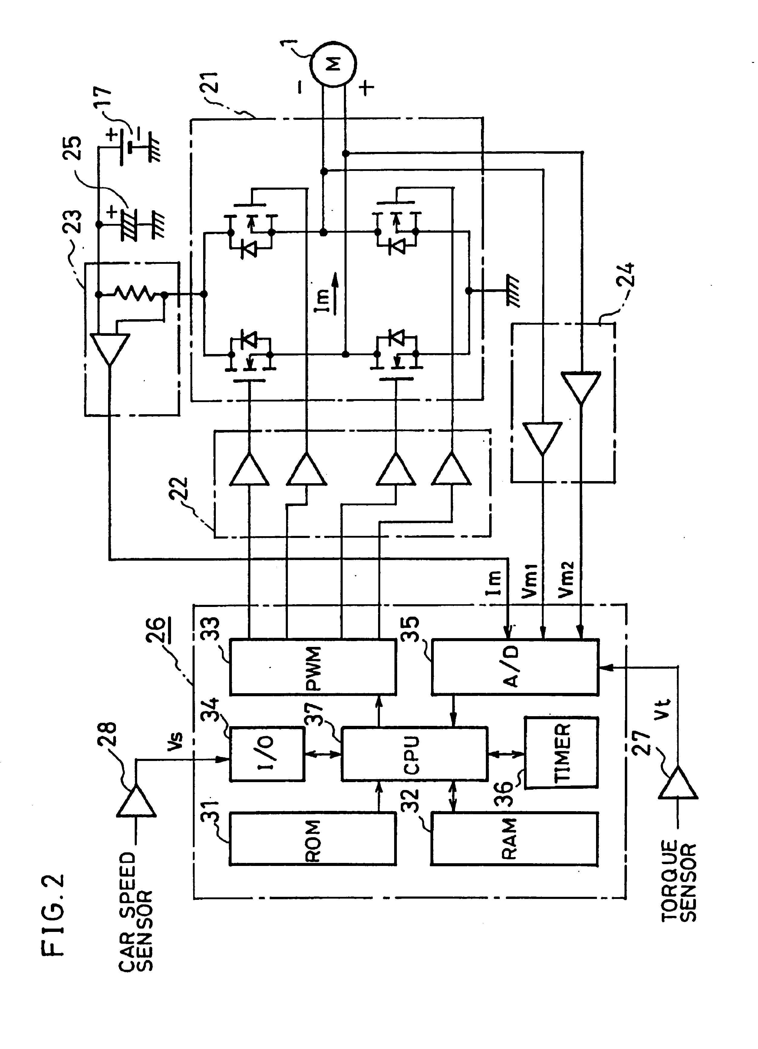
FIG. 2 is a diagram showing the constitution of the hardware of the controller 16. In FIG. 2, reference numeral 21 represents a motor d...
embodiment 2
In the above Embodiment 1, the static friction of the steering system is estimated by extracting the edge of the steering torque detection value Vf. The same effect can be obtained by extracting the edge of the angular velocity of the steering system. The angular velocity may be motor angular velocity ω, back electromotive force Ve, steering speed or the like. In this Embodiment 2, the static friction of the steering system is estimated by extracting the edge of the angular velocity of the steering system. Therefore, the static friction can be estimated without being influenced by the noise of the torque sensor 14.
embodiment 3
In the above Embodiment 1, the static friction of the steering system is estimated by extracting the edge of the steering torque detection value Vf. The same effect can be obtained by extracting the edge of a motor current. The motor current encompasses not only a motor detection current Im but also a compensation current such as a steering force assist current Is.
For instance, when a static friction compensation current If is computed based on the edge of a steering force assist current Is which is a current constituting a motor target current Isum, appropriate static friction compensation can be made on steering assist force as the static friction compensation current If changes according to steering assist force at a car speed Vs as shown in FIG. 17.
When a static friction compensation current If is computed based on a motor target current Isum or a motor detection current Im, the static friction of the motor 1 can be compensated more accurately as the static friction is detected ...
PUM
 Abstract
Description
Claims
Application Information