
Memory testing method and memory testing apparatus

a memory testing and memory technology, applied in the direction of error detection/correction, digital storage, instruments, etc., can solve the problems of increasing the time duration required for carrying out failure repair analysis, increasing the time duration required for carrying out rewriting operations, and increasing the time duration required for testing flash memory in proportion to the number of failure memory cells

Inactive Publication Date: 2005-04-05
ADVANTEST CORP
View PDF11 Cites 43 Cited by
  • Summary
  • Abstract
  • Description
  • Claims
  • Application Information

AI Technical Summary

Benefits of technology

The present invention provides a memory testing method and apparatus that can quickly determine if a memory has failed and can decide whether to repair the failure or not. This saves time and reduces the amount of testing required. The method and apparatus can also decide to interrupt the testing of a block if the number of failure memory cells reaches a predetermined level, and can transfer the testing to the next block if there are multiple failures. This further reduces the testing time.

Problems solved by technology

Consequently, there is a drawback that the time duration required for carrying out the failure repair analysis becomes considerably long.
Accordingly, there is a drawback that the time duration required for carrying out the rewriting operations becomes considerably long.
As a result, there is an important defect that the time duration required for testing a flash memory becomes long in proportion to the number of failure memory cells.
Accordingly, there is a serious drawback that the remaining flash memories spend a waste of time, which results in longer test time.
Accordingly, the aforesaid drawback resulting in longer test time eventually brings about an increase of the testing cost.

Method used


Image

  • Memory testing method and memory testing apparatus
  • Memory testing method and memory testing apparatus
  • Memory testing method and memory testing apparatus

Examples


Embodiment Construction

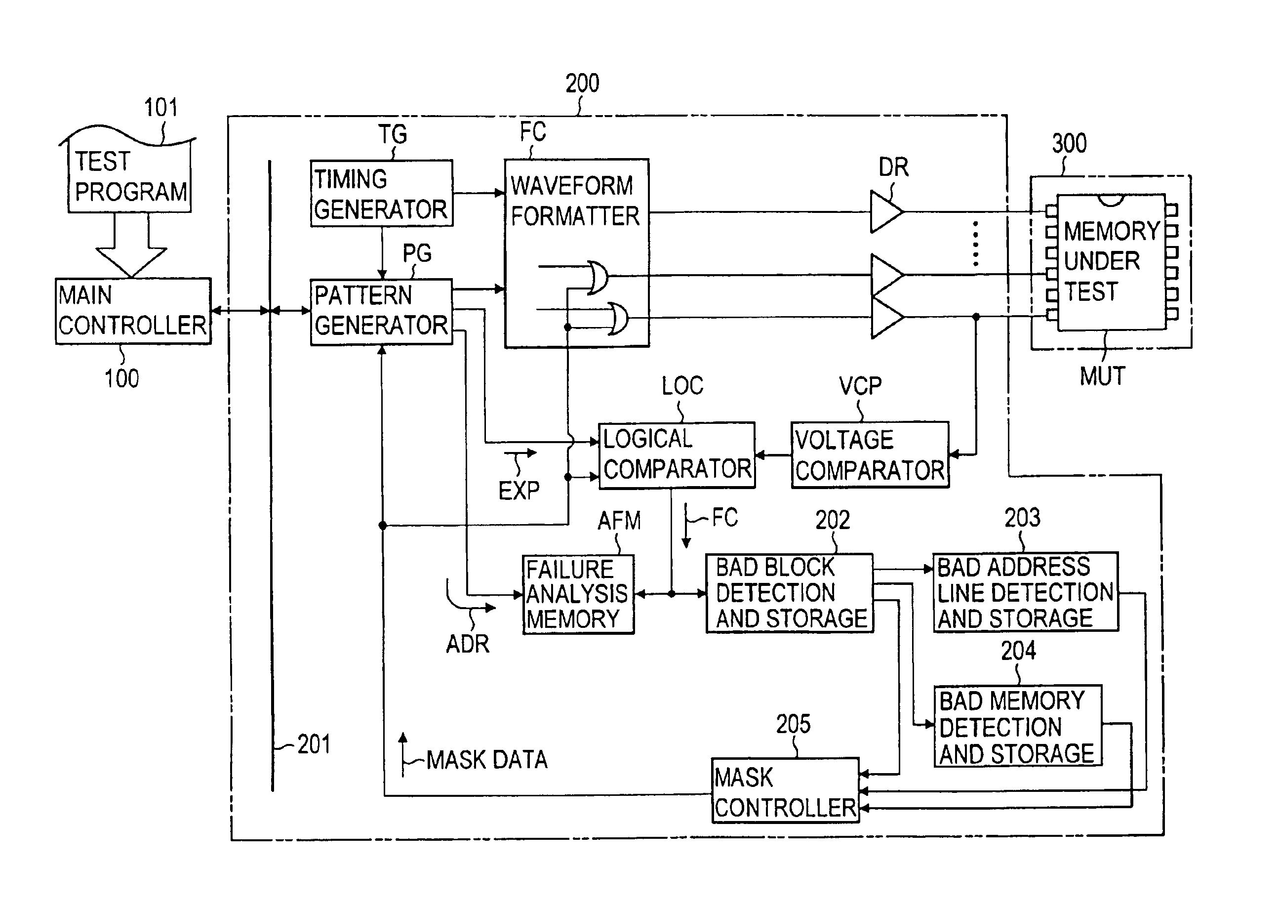
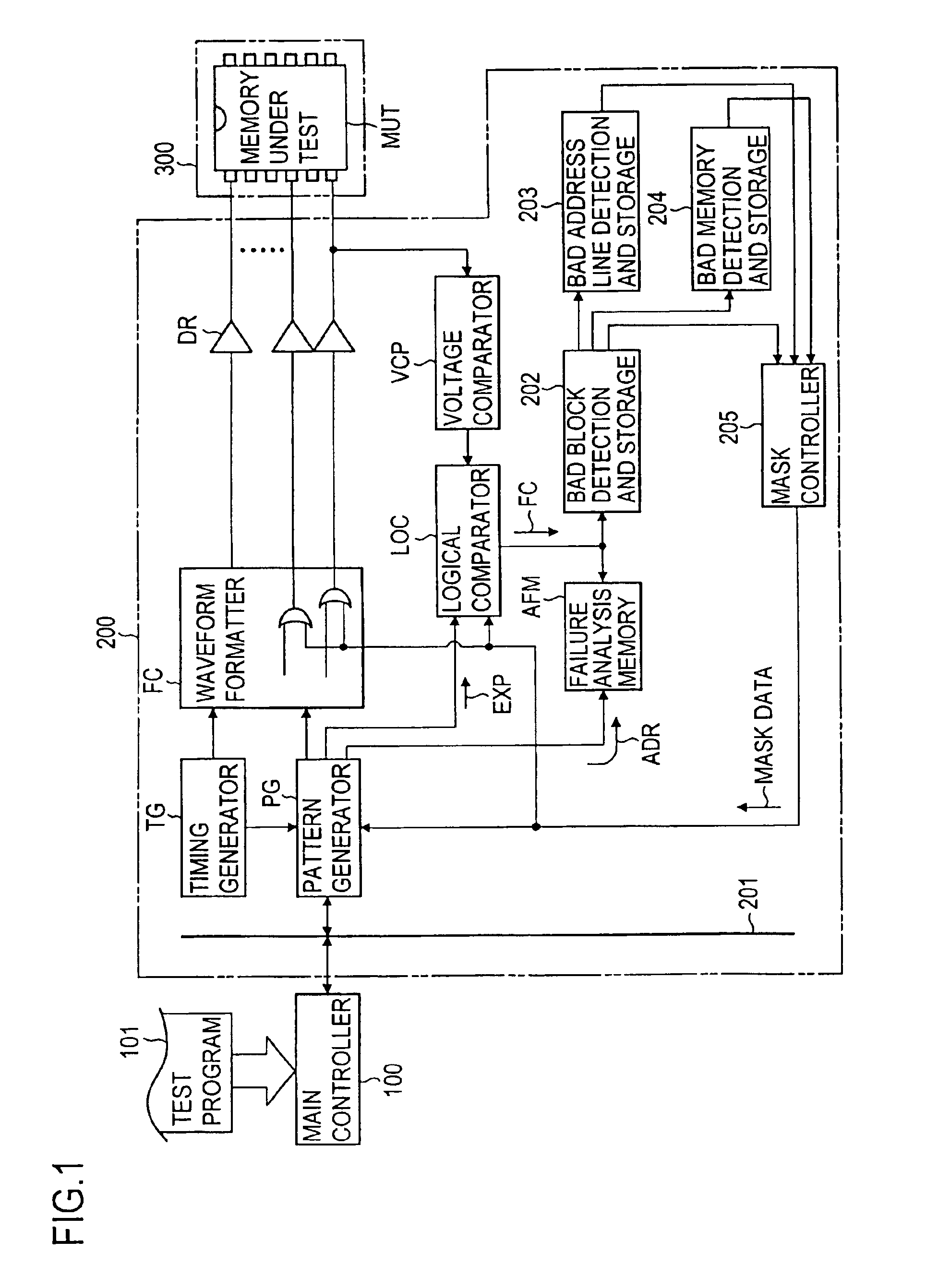
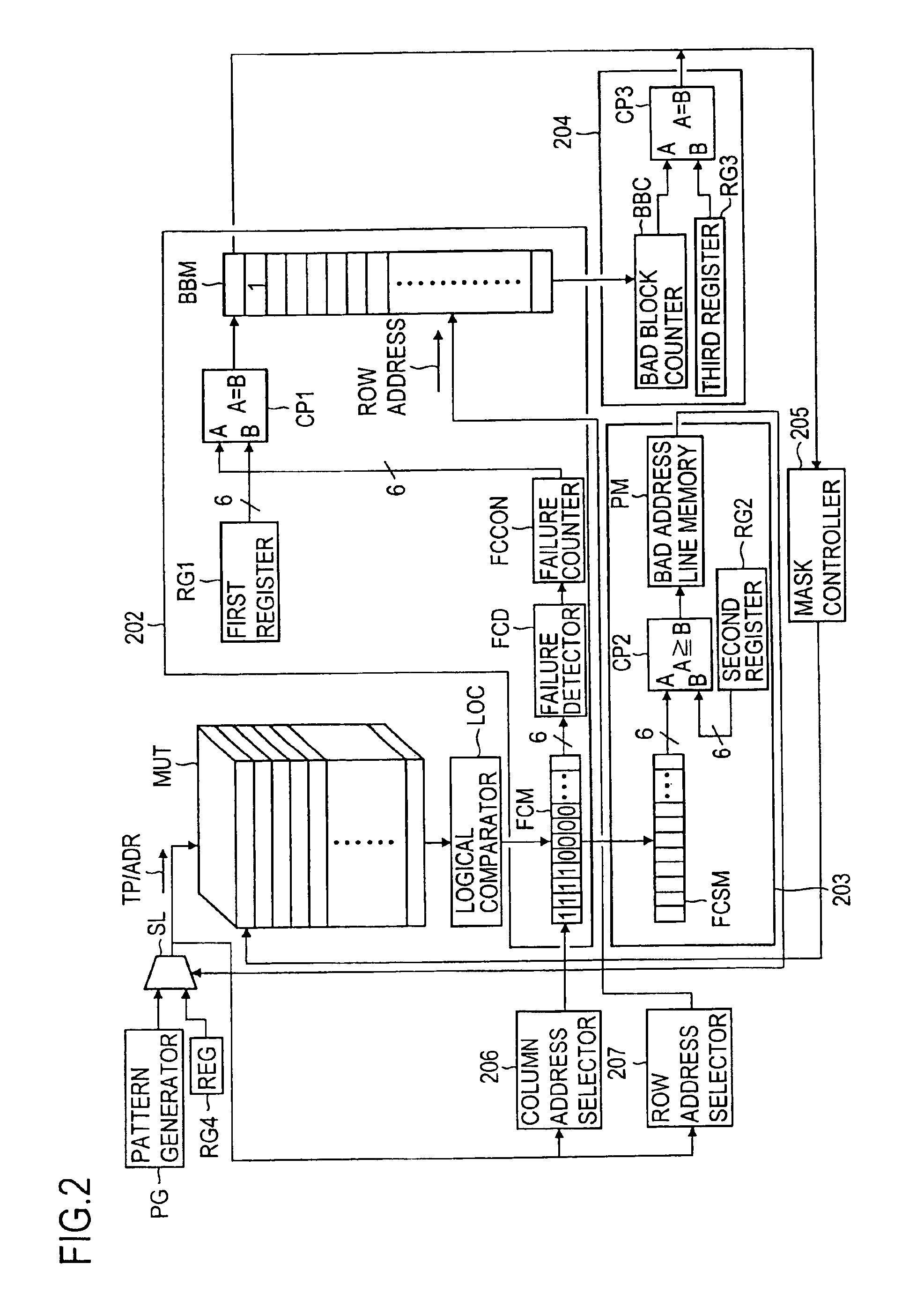
Now, the preferred embodiment of the memory testing apparatus according to the present invention will be described in detail with reference to FIGS. 1 to 3. The present invention may, however, be embodied in many different forms and should not be construed as limited to the embodiment set forth hereinafter; rather, the embodiment is provided so that this disclosure will be thorough and complete, and will fully convey the scope of the invention to those skilled in the art. Further, portions or elements in FIGS. 1 and 3 corresponding to those in FIGS. 5 and 6 will be shown by the same reference characters affixed thereto, and the explanation thereof will be omitted unless it is necessary.

FIG. 1 shows, in block diagram form, an embodiment of the memory testing apparatus according to the present invention. Like the prior memory testing apparatus shown in FIG. 5, the memory testing apparatus of this embodiment is also constituted by a main controller 100, a testing apparatus proper (here...


PUM


Abstract

A memory testing method and apparatus are provided, which can test in short time a flash memory. In case of testing a flash memory having block function, in a memory testing method and apparatus in which a predetermined logical value is written in memory cells constituting each of blocks of the memory, the written logical value is read out from the memory cells to compare it with an expected value, and a decision that, when the read-out logical value and the expected value do not coincide with each other, such memory cell is a failure memory cell, a decision is rendered that, when the number of failure memory cells in each block reaches a predetermined number, such block is a bad block, and the test of such block is stopped. In addition, a decision is rendered that, when the number of failure memory cells on the same address line reaches a predetermined number, such address line is a bad address line, and after such decision has rendered, the test of memory cells on the bad address line is substantially not effected.

Description

BACKGROUND OF THE INVENTION1. Field of the InventionThe present invention relates to a memory testing method and a memory testing apparatus for testing a memory having block function called, for example, a flash memory that the stored data therein can be electrically erased in all bits en bloc or in block by block en bloc and new data can be rewritten therein.2. Description of the Related ArtAmong PROMs (programmable read only memories) which are rewritable read only memories is called “flash memory” in this technical field a memory the stored contents of which are replaceable by electrically erasing the stored contents in all bits en bloc or in block by block en bloc and rewriting data therein. As shown in FIG. 4, such flash memory has its internal structure separated into a plurality of blocks (in this example, 1024 blocks from block No. 1 to block No. 1024). Each of the blocks is constituted by N pages (N is an integer equal to or greater than 2), and each of the N pages is const...

Claims


Application Information

Patent Timeline
Patent Type & Authority Patents(United States)
IPC IPC(8): G11C29/56G11C29/00G06F11/22G01R31/28G06F12/16G11C16/06G11C29/44
CPCG11C29/56G11C29/82G11C29/00
Inventor OSHIMA, HIROMIOKINO, NOBORUKAWATA, YASUHIRO
Owner ADVANTEST CORP
Learn More