Riveting method

Inactive Publication Date: 2005-04-12
SUN MICROSYSTEMS INC
View PDF10 Cites 30 Cited by
  • Summary
  • Abstract
  • Description
  • Claims
  • Application Information

AI Technical Summary

Benefits of technology

Thus, the method according to the invention has the advantage that access is only necessary to one side of the metal sheets to be joined (the working side) but that it is possible to form a rivet joint that does not protrude on the other surface of the sheets that are joined (the blind side).

Problems solved by technology

In addition, a point of weakness called a breakneck may be provided in the mandrel in the region of the rivet sleeve.
It is not economically feasible to join the various sheets forming the internal and external walls of the housing by spot welding because this would require re-plating of the steel sheets after welding.
Also, it is not possible to employ usual rivets in such an assembly because this would require access to both sides of the sheets to be joined by a relatively large “l” shaped anvil of a setting tool.
However the formation of protuberances on both surfaces of the sheets to be joined by the rivets is not compatible with the requirement to be able to slide the various components into and out of the chassis, nor is it compatible with the proximity of various joined metal sheets forming internal partitions or bulkheads to other parts of the chassis.

Method used


Image

  • Riveting method
  • Riveting method
  • Riveting method

Examples


Embodiment Construction

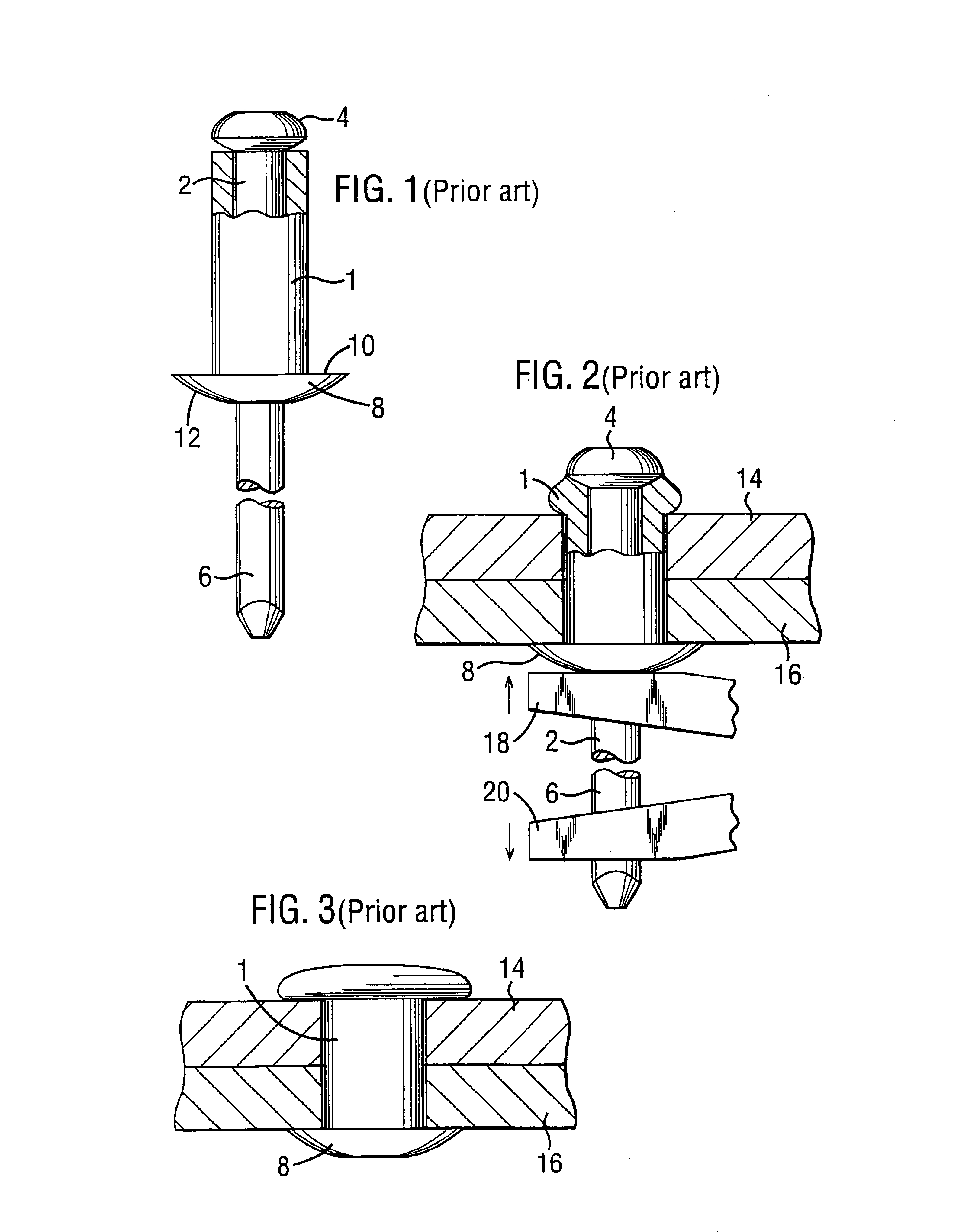
Referring now to the drawings, in which like reference numerals are used to designate corresponding elements, FIG. 1 shows a conventional form of blind rivet. The rivet comprises a hollow sleeve 1 having a throughbore for receiving a mandrel 2 that extends through it and terminates at one end in a head 4. At its other end the mandrel extends beyond the end of the sleeve 2 and becomes a pulling stem 6 that can be gripped by a rivet setting tool. At the end opposite the mandrel head 4, the sleeve 1 has a radially extending flange 8 having a flat inwardly facing surface 10 and a slightly domed outwardly facing surface 12.

In operation, in order to form a rivet joint between metal sheets 14 and 16, the rivet is inserted into a hole that has been drilled through the sheets starting with the head 4 of the mandrel until the surface 10 of the flange 8 abuts the outwardly facing surface of the sheet 16. The rivet is then set by means of a setting tool having a pair of jaws 18 and 20. One of t...


PUM

PropertyMeasurementUnit
Forceaaaaaaaaaa

Abstract

A method of joining a plurality of sheets by means of a blind rivet, comprises:(i) forming holes in the sheets and placing the sheets together so that the holes are in register and form a single hole therethrough;(ii) inserting a blind rivet into the hole formed in the sheets from a working side thereof, the blind rivet comprising a sleeve (1) positioned about a mandrel that has a head (4); and(iii) setting the rivet.The hole (24) is radially enlarged at the outwardly facing surface of at least the sheet on the blind side, and the sleeve of the rivet is deformed during setting to form a rivet joint in which no part of the rivet is proud of the outwardly facing surface (28) of the sheet at least on the blind side of the sheets. The method enables rivet joints to be formed in sheets, for example used in enclosures that house modules, where there is no space available for the set rivets to protrude.

Description

BACKGROUND OF THE INVENTIONThe present invention relates to methods of forming rivet joints.Rivets and methods of joining metal sheets together employing rivets have been known for many years, and involve inserting a rivet into aligned holes drilled through the sheets followed by deforming the rivet by compression so that it expands radially on either side of the sheets and holds them together. Where access to only one side of the sheets is easily available, it is usual to employ a blind rivet for forming the joint. A typical blind rivet comprises a sleeve formed from the rivet material that is located about a mandrel having an enlarged head at one end. Usually the mandrel extends some distance beyond the other end of the rivet sleeve as a pulling stem, and a radially extending flange is provided on the end of the rivet sleeve opposite to the mandrel head. In addition, a point of weakness called a breakneck may be provided in the mandrel in the region of the rivet sleeve. The blind ...

Claims


Application Information

Patent Timeline
IPC IPC(8): B21J15/00B21J15/04F16B19/04F16B19/10F16B5/04F16B5/00H05K3/36
CPCB21J15/043F16B5/04F16B19/1054Y10T403/49Y10T29/49956Y10T29/4992Y10T29/49943H05K3/365
Inventor SCHNABEL, JOHN DAVIDSPARKES, STEPHEN DAVID
Owner SUN MICROSYSTEMS INC
Why Eureka
Try Eureka