Method and device for checking a marking element for displacement

a marking element and method technology, applied in the direction of instruments, applications, person identification, etc., can solve problems such as compromise of operation, and achieve the effect of the greatest possible precision

Inactive Publication Date: 2005-04-12
AESCULAP AG
View PDF17 Cites 76 Cited by
  • Summary
  • Abstract
  • Description
  • Claims
  • Application Information

AI Technical Summary

Benefits of technology

It is a further advantage of the invention that an apparatus of the type mentioned in the introduction for checking a marking element for displacement in relation to the holding structure, said marking element functioning with the greatest possible precision is made available. According to the invention, this is achieved by an apparatus which comprises a navigation device for determining the position of the marking element in space, a device for establishing and / or determining a point of orientation which is in a defined relationship to the holding structure, a device which determines the position of the point of orientation in the reference system of the marking element, and a detection device for checking the marking element for displacement by checking the point of orientation for positional displacement.
The position of the marking element is in any case determined via the navigation, so that the reference system of the marking element, that is to say the rest system of the marking element, is known. By establishing an additional point, namely the point of orientation, which is in a unique and determinable relationship to the holding structure, it is thus possible, by periodical or in particular continuous monitoring of the point of orientation for movement in the reference system of the marking element, to detect a displacement of the latter. If such a displacement is established, then the result of the operation is compromised if said operation is continued without appropriate corrections, because the position indicated by the displaced marking element no longer correlates with the starting position at which the calibration took place. By means of the method according to the invention, a computer-assisted operation can consequently be monitored and, if a displacement is detected, an operator is then informed of the fact that, before continuing the operation, a suitable corrective measure is required because the position of a marking element has moved.
By means of the procedure according to the invention, namely involving choosing a point of orientation in a defined and determinable relationship to the holding structure, only the movement of this point of orientation has to be detected to check for displacement. Since, as has already been mentioned, the position of the marking element is in any case determined continuously by the navigation station, the “positional tracking” of a single point, namely the point of orientation, is accordingly sufficient to carry out a safety check for displacement of each marking element.
The following description of a preferred embodiment serves, together with the drawing, to further explain the invention.

Problems solved by technology

If such a displacement is established, then the result of the operation is compromised if the operation is continued without appropriate corrections, because the position indicated by the displaced marking element no longer correlates with the starting position at which the calibration took place.

Method used


Image

  • Method and device for checking a marking element for displacement
  • Method and device for checking a marking element for displacement
  • Method and device for checking a marking element for displacement

Examples


Embodiment Construction

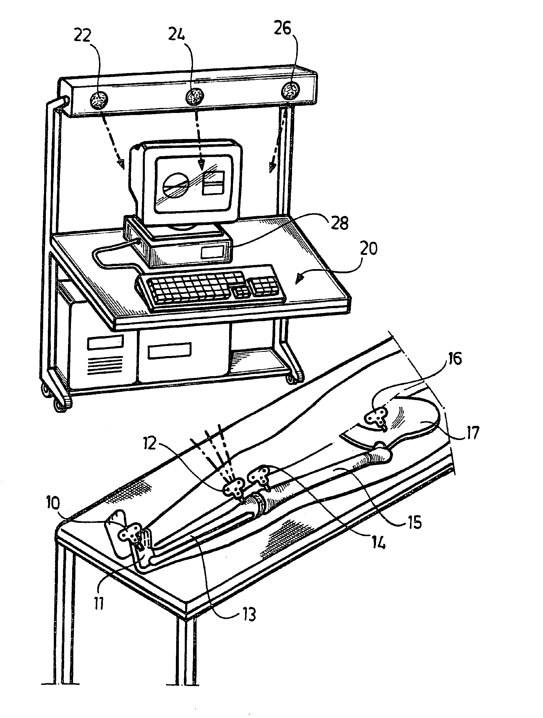
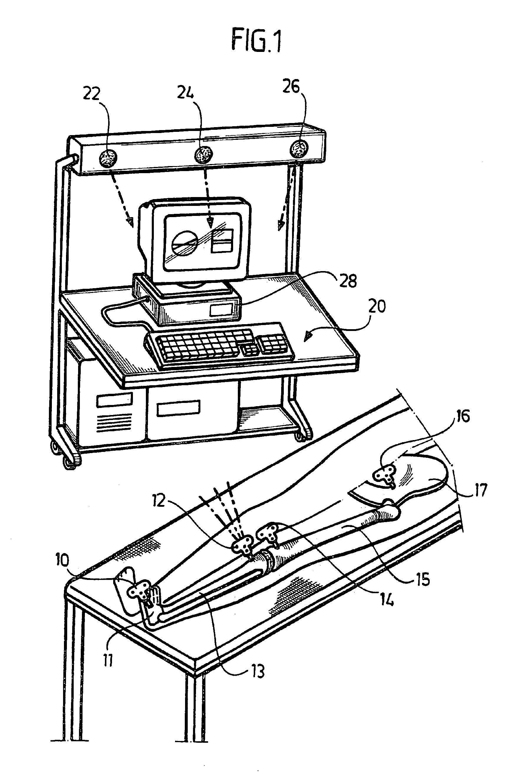
In computer-assisted surgery (navigational surgery), operating robots are used in order, for example, to ream out bone cavities with a defined arrangement and size or to saw through bone in defined spatial sections. Typical fields of application are operations for implanting endoprostheses. To ensure that the corresponding operating procedures can be executed with a high degree of precision and with the desired result, the spatial position of the machining tool relative to the patient's body must be established; it must in particular be constantly monitored and, if appropriate, corrected.

For positional determination in navigational surgery, marking elements are provided, as are shown for example in FIG. 1. In an operation, for example, one marking element 10 sits on the foot bone 11, one marking element 12 on the bone 13 of the lower leg, one marking element 14 on the femoral bone 15, and one marking element 16 on a hip bone 17.

The bones 11, 13, 15, 17 in each case form a holding st...


PUM


Abstract

To make available a method for checking a marking element for displacement in relation to a holding structure, in particular a bone, on which this marking element is fixed, said marking element being used for determining position in navigational surgery, and said marking element functioning with the greatest possible precision, it is proposed to choose a point of orientation which is in a unique relationship to the holding structure and to monitor the position of the point of orientation in a reference system of the marking element.

Description

The present disclosure relates to the subject matter disclosed in German application No. 101 45 587.9 of Sep. 15, 2001, which is incorporated herein by reference in its entirety and for all purposes.BACKGROUND OF THE INVENTIONThe invention relates to a method and a device for checking a marking element for shift or displacement in relation to a holding structure, in particular a bone, on which this marking element is fixed, said marking element being used for determining position in navigational surgery.In navigational surgery (computer-assisted surgery), robots are used in order, for example, to ream out bone cavities or to make incisions in bone or to saw through bone. By this means, the site of the reaming or the site of the incision can be set with precision. To do so, however, it is necessary that the spatial positions of the machining tools relative to the operating field are known at each point in time with a high degree of accuracy.For this purpose, marking elements are used...

Claims


Application Information

Patent Timeline
Patent Type & Authority Patents(United States)
IPC IPC(8): A61B19/00A61B5/103G01S5/16G01S5/18G01S5/00A61B17/00A61B34/20A61B90/00
CPCA61B19/52G01S5/163G01S5/18A61B5/4504A61B19/50A61B19/5244A61B2017/00725A61B2019/4863A61B2019/5272A61B2019/5483A61B2019/5255A61B2090/3983A61B90/36A61B2034/2055A61B2034/2072A61B34/20A61B2090/0812A61B34/10
Inventor LEITNER, FRANCOISMOLLARD, BENOIT
Owner AESCULAP AG
Why Eureka
Try Eureka