Double end servo scroll and direct scroll driver pattern attachment for tufting machine

a tufting machine and double-end servo technology, applied in the direction of embroidering machines, sewing apparatus, textiles and paper, etc., can solve the problems of high gear ratio, many limitations of roll-type pattern devices, and high cost, and achieve the effect of reducing costs

Inactive Publication Date: 2005-04-12
TUFTCO
View PDF1 Cites 37 Cited by
  • Summary
  • Abstract
  • Description
  • Claims
  • Application Information

AI Technical Summary

Benefits of technology

It is a further object of this invention to provide a pattern controlled yarn feed mechanism

Problems solved by technology

There are many limitations on roll-type pattern devices.
Perhaps the most significant limitations are: (1) as a practical matter, there is not room on a tufting machine for more than about eight pairs of yarn feed rolls; (2) the yarn feed rolls can be driven at only one of two, or possibly three speeds, when the traditional construction utilizing clutches is used—a wider selection of speeds is possible when using direct servo motor control, but powerful motors and high gear ratios are required and the shear mass involved makes quick stitch by stitch adjustments difficult; and (3) the threading and unthreading of the respective yarn feed rolls is very time consuming as yarns must be fed between the yarn feed rolls and cannot simply be slipped over the end of the rolls, although the split roll configuration of Watkins, U.S. Pat. No. 4,864,946 addresses this last problem.
The use of yarn feed tubes introduces additional complexity and e

Method used


Image

  • Double end servo scroll and direct scroll driver pattern attachment for tufting machine
  • Double end servo scroll and direct scroll driver pattern attachment for tufting machine
  • Double end servo scroll and direct scroll driver pattern attachment for tufting machine

Examples


Embodiment Construction

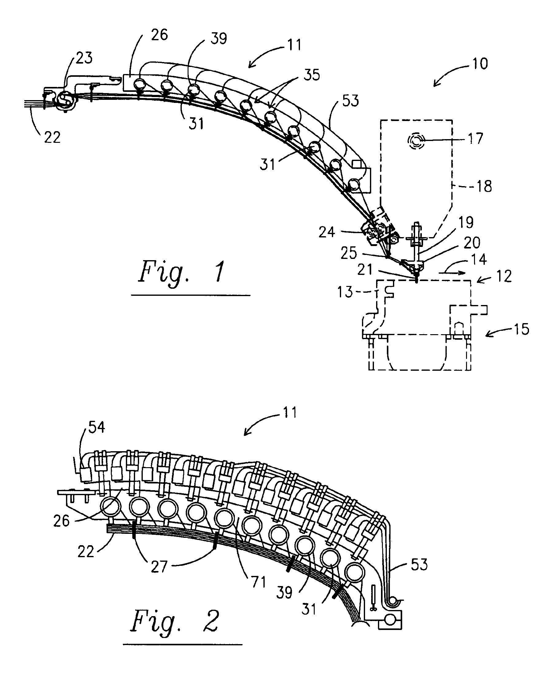
Referring to the drawings in more detail, FIG. 1 discloses a multiple needle tufting machine 10 upon the front of which is mounted a pattern control yarn feed attachment 11 in accordance with this invention. It will be understood that it is possible to mount pattern control yarn feed attachments 11 on both sides of a tufting machine 10 when desired. The machine 10 includes a housing 12 and a bed frame 13 upon which is mounted a needle plate, not shown, for supporting a base fabric adapted to be moved through the machine 10 from front to rear in the direction of the arrow 14 by front and rear fabric rollers. The bed frame 13 is in turn mounted on the base 15 of the tufting machine 10.

A main drive motor drives a rotary main drive shaft 17 mounted in the head 18 of the tufting machine. Drive shaft 17 in turn causes push rods 19 to move reciprocally toward and away from the base fabric. This causes needle bar 20 to move in a similar fashion. Needle bar 20 supports a plurality of prefera...


PUM


Abstract

The present invention provides a double end yarn drive pattern attachment for tufting machines characterized by independent servo-motor control of yarn feed rolls capable of increased torque to carry multiple yarn ends on a single feed roll, thereby economically retaining many advantages of a single end pattern attachment. The improved attachment utilizes an intermediate gear to provide a relatively high torque drive adaptable between single and plural yarn pattern attachments.

Description

BACKGROUND OF THE INVENTIONThis invention relates to a yarn feed mechanism for a tufting machine and more particularly to a scroll-type pattern controlled yarn feed where about two to five yarns may be wound on a separate yarn feed roll, and each yarn feed roll is driven by an independently controlled servo motor; or for providing a high torque single end yarn feed roll drive.Pattern control yarn feed mechanisms for multiple needle tufting machines are well known in the art and may be generally characterized as either roll-type or scroll-type pattern attachments. Roll type attachments are typified, by J. L. Card, U.S. Pat. No. 2,966,866 which disclosed a bank of four pairs of yarn feed rolls, each of which is selectively driven at a high speed or a low speed by the pattern control mechanism. All of the yarn feed rolls extend transversely the entire width of the tufting machine and are journaled at both ends. There are many limitations on roll-type pattern devices. Perhaps the most s...

Claims


Application Information

Patent Timeline
IPC IPC(8): D05C15/18D05C15/32D05C15/00
CPCD05C15/32D05C15/18
Inventor FROST, STEVENPRICHARD, RICHARD
Owner TUFTCO
Why Eureka
Try Eureka