
Vacuum regulating valve

a technology of vacuum regulating valve and valve plug, which is applied in the direction of valve sealing, spindle operation/release device, mechanical equipment, etc., can solve the problems of unsatisfactory operation efficiency and extremely time-consuming operation, and achieve the effect of improving the maintenance performance of the valve plug and controlling the flow ra

Inactive Publication Date: 2005-04-12
SMC CORP
View PDF12 Cites 19 Cited by
  • Summary
  • Abstract
  • Description
  • Claims
  • Application Information

AI Technical Summary

Benefits of technology

[0012]A general object of the present invention is to provide a vacuum regulating valve which makes it possible to improve the maintenance performance of a valve plug. The valve plug controls the flow rate of a fluid flowing through a communication passage by being seated on a valve seat and being separated from the valve seat.

Problems solved by technology

This operation is also extremely time-consuming.
Therefore, operation efficiency is unsatisfactory when the main valve body 5 is maintained.

Method used


Image

  • Vacuum regulating valve
  • Vacuum regulating valve
  • Vacuum regulating valve

Examples


Embodiment Construction

is further displaced upwardly;

[0020]FIG. 7 is, with partial omission, a vertical sectional view when the valve plug shown in FIG. 6 is still further displaced upwardly;

[0021]FIG. 8 is, with partial omission, a vertical sectional view illustrating a valve plug of a conventional vacuum regulating valve; and

[0022]FIG. 9 is, with partial omission, a vertical sectional view illustrating the valve plug shown in FIG. 8.

DESCRIPTION OF THE PREFERRED EMBODIMENTS

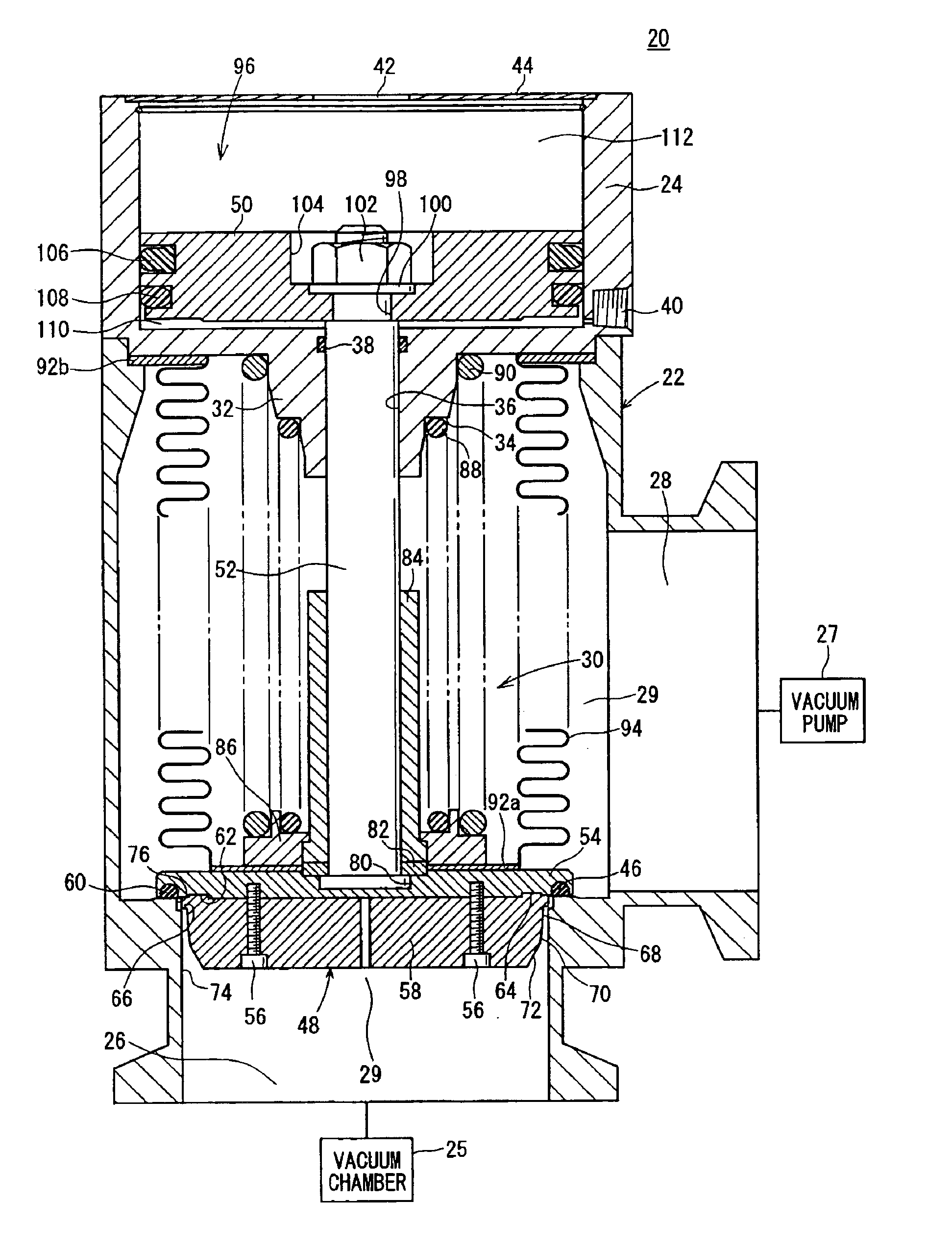
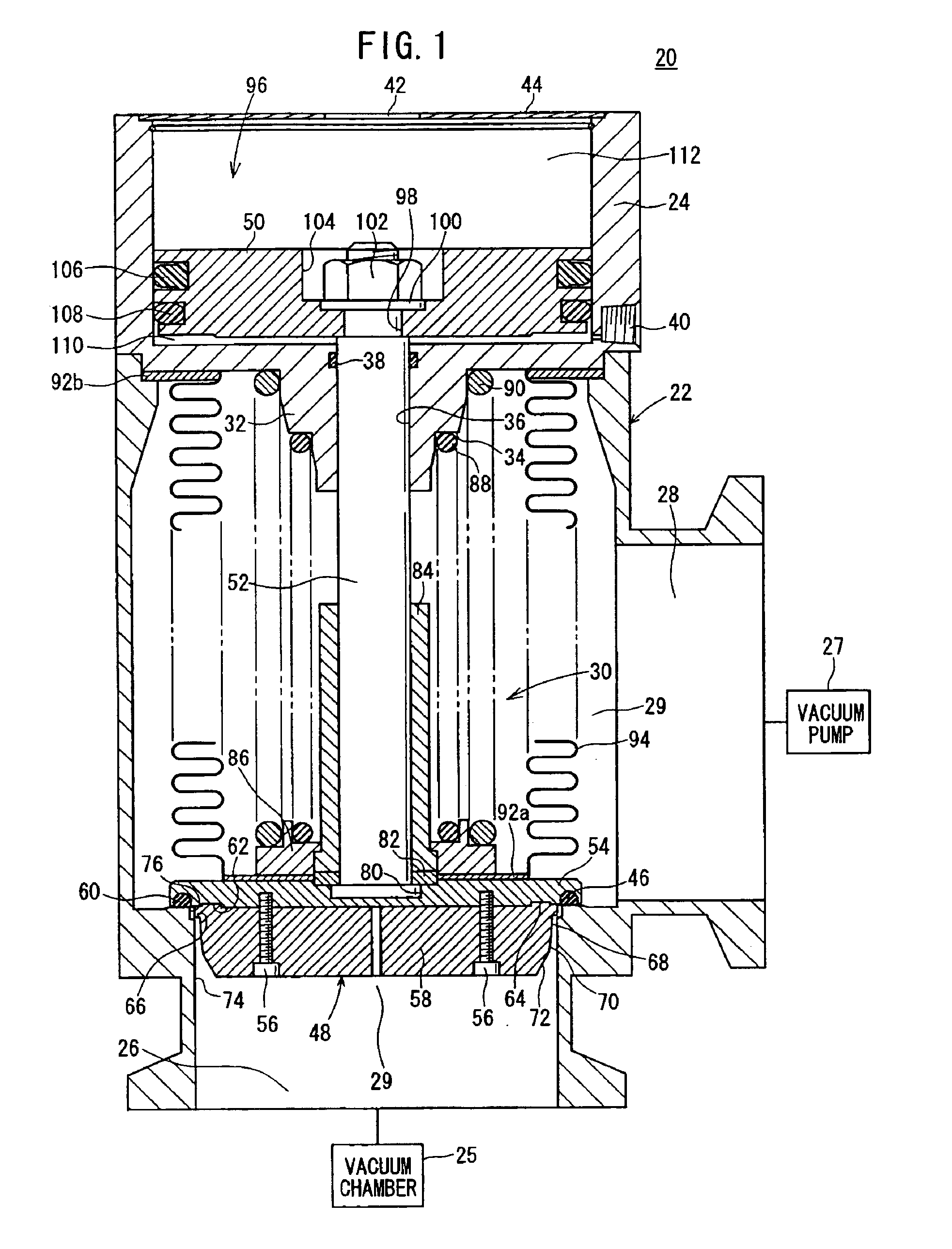
[0023]With reference to FIG. 1, reference numeral 20 indicates a vacuum regulating valve according to an embodiment of the present invention.

[0024]The vacuum regulating valve 20 comprises a substantially cylindrical valve body 22, a bonnet 24 connected to an upper portion of the valve body 22, a chamber port (first port) 26 formed at a lower portion of the valve body 22 and connected to a vacuum chamber 25, a pump port (second port) 28 formed on a side surface of the valve body 22 substantially perpendicularly to the axis and connected...


PUM


Abstract

A chamber port to which a vacuum chamber is connected and a pump port to which a vacuum pump is connected are formed on a valve body of a vacuum regulating valve. A valve plug includes a plate and a nose which is connected to the plate by screw members, and closes the chamber port by a pressure fluid. The maximum outer diameter of the nose is smaller than the inner circumferential diameter of the chamber port. The nose is detached through the chamber port.

Description

BACKGROUND OF THE INVENTION[0002]1. Field of the Invention[0003]The present invention relates to a vacuum regulating valve which is connected, for example, between a vacuum chamber and a vacuum pump to control flow rate so that the pressure in the vacuum chamber is gradually reduced to be a vacuum pressure.[0004]2. Description of the Related Art[0005]For example, the internal pressure of a vacuum chamber of an apparatus for processing a semiconductor wafer or the like may be lowered to a vacuum pressure by using a vacuum pump. In such a procedure, if the gas in the vacuum chamber at atmospheric pressure or high pressure is suddenly evacuated, a large amount of the gas temporarily flows. As a result, some gas turbulence may be generated in the vacuum chamber, and some produced material or the like on the inner wall surface of the vacuum chamber are peeled off. Then, the produced material may be adhered to the semiconductor wafer or the like, or scattered in fluid passages.[0006]In vi...

Claims


Application Information

Patent Timeline
IPC IPC(8): F16K41/00F16K41/10F16K51/02F16K1/52
CPCF16K51/02F16K41/10
Inventor KAJITANI, MASAO
Owner SMC CORP
Features
  • Generate Ideas
  • Intellectual Property
  • Life Sciences
  • Materials
  • Tech Scout
  • Unparalleled Data Quality
  • Higher Quality Content
  • 60% Fewer Hallucinations
Learn More