Folding bicycle

a bicycle and folding technology, applied in the field of folding bicycles, can solve the problems of difficult use and inconvenience, and achieve the effects of convenient use, simple operation, and convenient cushioning characteristics

Inactive Publication Date: 2005-04-12
ATORASU OOTO
View PDF16 Cites 19 Cited by
  • Summary
  • Abstract
  • Description
  • Claims
  • Application Information

AI Technical Summary

Benefits of technology

In this folding bicycle, the main frame is a single rod and there is no hinge portion to be folded in an intermediate part. Thus, it is not necessary to particularly consider a reinforcing structure of a folded portion, resulting in a simple configuration and weight reduction. Further, the folded portions are only the rotatably supported portions with respect to the main frame, of the saddle post, the stay, and the handle shaft, so that the folding can be performed with simple operations. Moreover, since all these members are folded along a single main frame, a folded-state shape can be smaller.
Further, when the stay is attached and detached to and from the saddle post via a suspension mechanism, it is possible to achieve preferable cushioning characteristics and comfortable riding.

Problems solved by technology

Therefore, the bodies become heavier and complicated operations are necessary during assembling and folding, posing a problem such that convenient use is difficult.

Method used


Image

  • Folding bicycle
  • Folding bicycle
  • Folding bicycle

Examples


embodiment 1

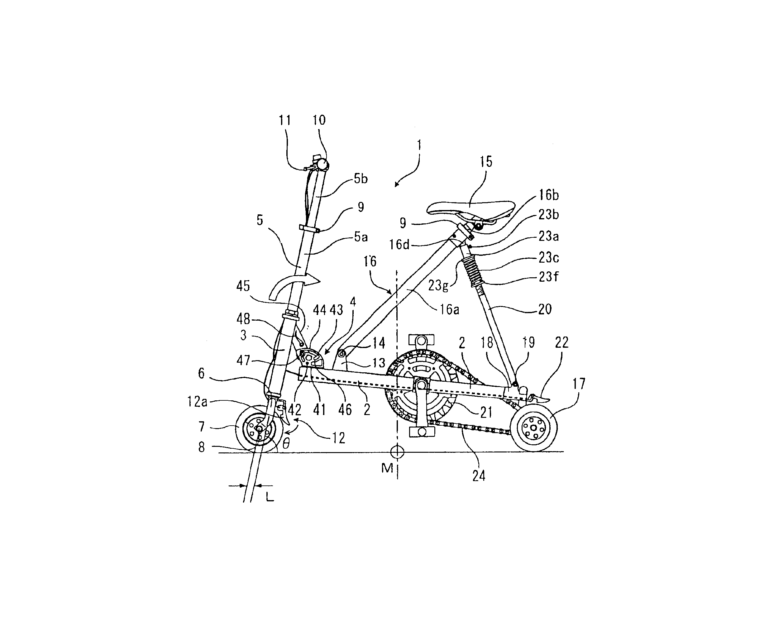
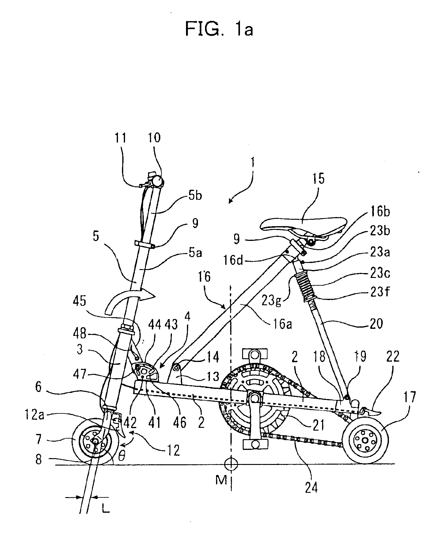
As shown in FIG. 1a, a folding bicycle 1 has a head pipe 3 on the front end of a main frame 2 shaped like a rod. As indicated by an arrow, the head pipe 3 can be freely rotated by a hinge member 4 inside a surface including the main frame 2.

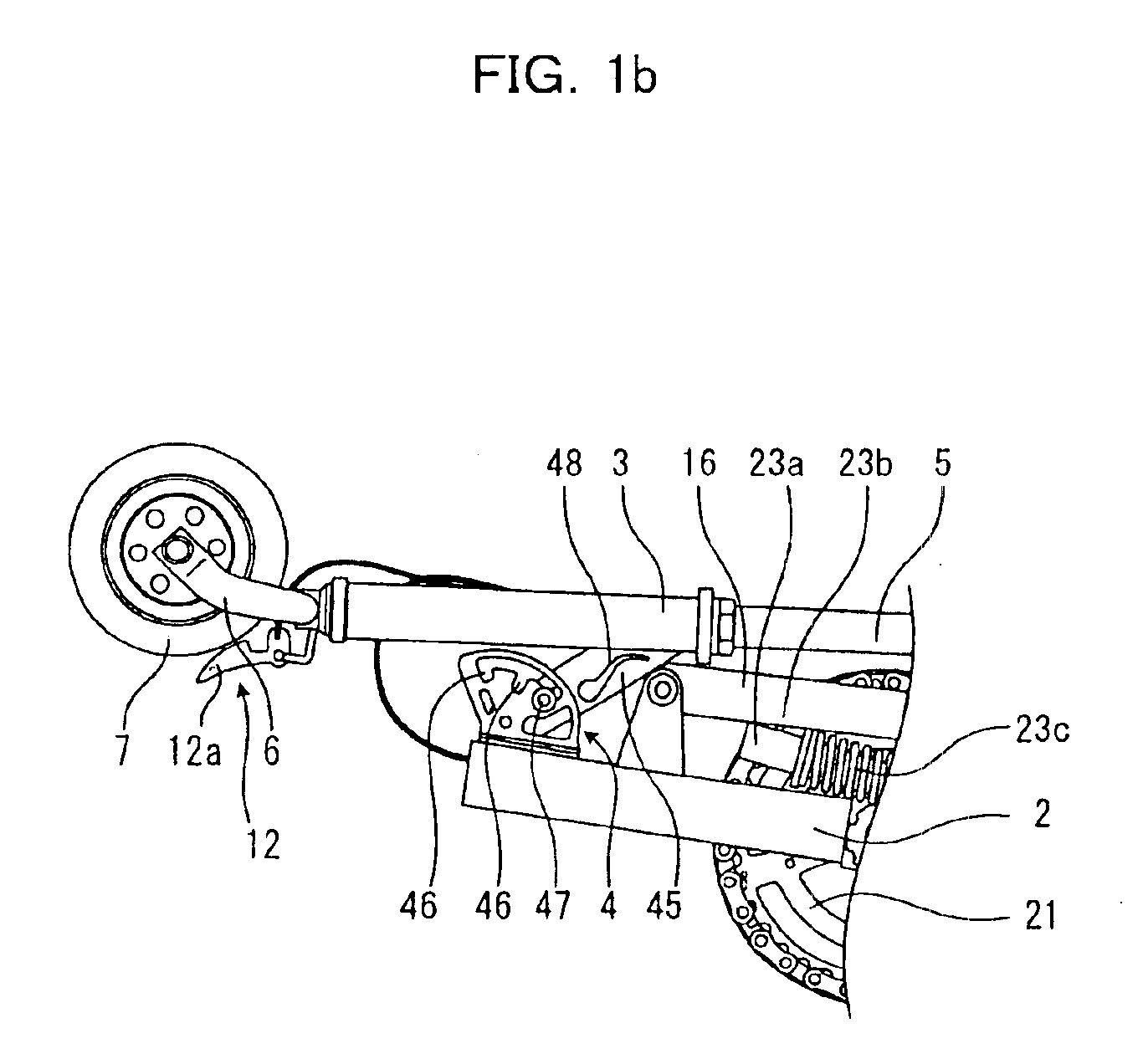
The hinge member 4 has guide plates 44 raised so as to be opposed to each other on both sides of a base 41 mounted on a surface of the main frame 2. The guide plate 44 has a guide groove 43 along the periphery having a pivot point 42 at the center. A supporting arm 45 is pivotally supported between the guide plates 44 so as to rotate about the pivot point 42.

The head pipe 3 is integrally attached to the end of the supporting arm 45 by welding and so on.

Then, notches 46 are formed on both ends of the guide groove 43 of the guide plate 44, and a pin 47 guided along the guide groove 43 is provided on the side of the supporting arm 45. The attitude of a handle shaft 5 can be adjusted by resiliently fitting the pin 47 into the notch 46.

In the figure, ...

embodiment 2

FIGS. 4a and 4b are side views showing a main part of a folding bicycle according to Embodiment 2, and FIG. 5 is a plan view showing a main part of the bicycle.

The folding bicycle of Embodiment 2 is similar in configuration to that of Embodiment 1 except for the configuration of a supporting part on a front wheel. Thus, the same parts are indicated by the same reference numerals and the detailed explanation thereof will be omitted.

In FIG. 4a, the folding bicycle of Embodiment 2 has a head pipe 3 fixed by welding on the front end of a main frame 2 with a fixed caster angle θ. A front wheel fork 6 is supported on the head pipe 3 so as to freely rotate about the shaft.

Further, a handle 5 is mounted on a supporting arm 45 of a hinge member 4 provided on the main frame 2. When the handle 5 is raised, the handle 5 is placed on the same axis as the front fork 6 which is supported by the head pipe 3. Moreover, as shown in FIG. 5, a square insertion hole 6p is provided on the upper end face ...

embodiment 3

FIG. 8 shows a side view showing a main part of a folding bicycle according to Embodiment 3.

The folding bicycle of Embodiment 3 is also similar in configuration to the folding bicycle of Embodiment 1 except for a supporting part of a front wheel. Thus, the same parts are indicated by the same reference numerals and the detailed description thereof will be omitted.

In FIG. 8, in the folding bicycle of Embodiment 3, a shaft 5c of a raised handle shaft 5 and a shaft 3a of a head pipe 3 are offset. Between the offset shafts, a rotation transmitting mechanism 23 is provided for transmitting the rotation of the handle shaft 5 to a fork 6 rotatably supported by the head pipe 3.

The rotation transmitting mechanism 23 in the illustrated example is a gear mechanism, in which a single intermediate gear 23H is interposed between gears 23T, so that a rotation is transmitted at a rotation ratio of 1:1 in the same direction as the handle shaft 5.

In this case, since it is not always necessary to alig...


PUM


Abstract

A folding bicycle, wherein a head pipe is pivotally supported on the front end of a main frame so as to freely rotate, a handle shaft for rotatably supporting a front wheel is supported while being inserted into the head pipe, a rear wheel is rotatably supported on the rear end of the main frame, a saddle post having a saddle on the top end is pivotally supported on the rear side of a pivotal-support portion of the head pipe, a stay having the top end detachably fixed on the saddle post is pivotally supported on the front side of the rear wheel of the main frame, a crank gear is rotatably supported between a pivotal-support portion of the saddle post and a pivotal-support portion of the stay, a chain is looped over the crank gear and a small gear provided on the rear wheel, and the stay, the saddle post and the handle shaft can be folded so as to be overlaid one another along the main frame.

Description

FIELD OF THE INVENTIONThe present invention relates to a folding bicycle.BACKGROUND OF THE INVENTIONA “bicycle” appearing in the tile of the invention is designed as a substantial “bicycle”. In particular, the “bicycle” of the invention is meant to include not only “bicycles” of the original meaning, but those two-wheeled vehicles that are not named “bicycle” because their wheels have diameters smaller than the minimum diameter required for wheels of standardized bicycles, or because they are provided with a power drive. The term “bicycle” thus meant is used throughout the specification and claims of this patent application.As described in JP2001-328581A and JP2001-278160A, a number of folding bicycles, which can be folded small and preferably stored when not being used, have been proposed and introduced on the market.Many of these folding bicycles have body frames, each being foldable between a front wheel and a rear wheel. When a folded part is assembled, in order to provide durab...

Claims


Application Information

Patent Timeline
Patent Type & Authority Patents(United States)
IPC IPC(8): B62K15/00
CPCB62K15/008B62K15/00
Inventor YAMABE, HIDEYASU
Owner ATORASU OOTO
Why Eureka
Try Eureka