Clamp for joining tubular bodies

a tubular body and band clamp technology, applied in the direction of sleeves/socket joints, mechanical equipment, machines/engines, etc., can solve problems such as discontinuous steps, and achieve the effect of good sealing and high pull-apart strength

Inactive Publication Date: 2005-04-12
BREEZE TORCA PRODS
View PDF41 Cites 67 Cited by
  • Summary
  • Abstract
  • Description
  • Claims
  • Application Information

AI Technical Summary

Benefits of technology

In accordance with this invention, a band clamp is provided for making a joint between tubular bodies which exhibits high pull-apart strength and also provides a good seal against fluid leakage. The band clamp includes a band extending from a first end to a second end and including a pair of spaced ribs extending at least part way between the first and second ends. A tightening mechanism is connected to the band and includes two clamp members movable toward and away from each other for tightening and loosening of the band. The band clamp further includes a gasket located on an inner surface of the band between the ribs and extending between the first and second ends. The use of the ribs with the interposed gasket provides a mechanical interlock of the band clamp with the tubular bodies being joined while providing a seal against the escape of fluid at the junction between the two bodies.

Problems solved by technology

Such an arrangement results in a discontinuous step at the inner terminal end of the band and can be problematic for applications where a strong hermetic seal is needed such as in vehicle exhaust systems.

Method used


Image

  • Clamp for joining tubular bodies
  • Clamp for joining tubular bodies
  • Clamp for joining tubular bodies

Examples


first embodiment

of this Invention

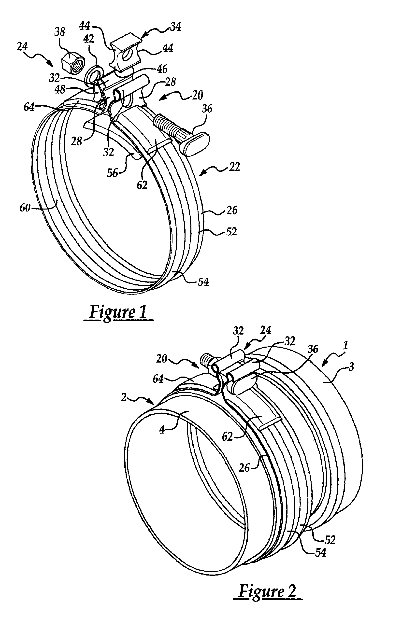
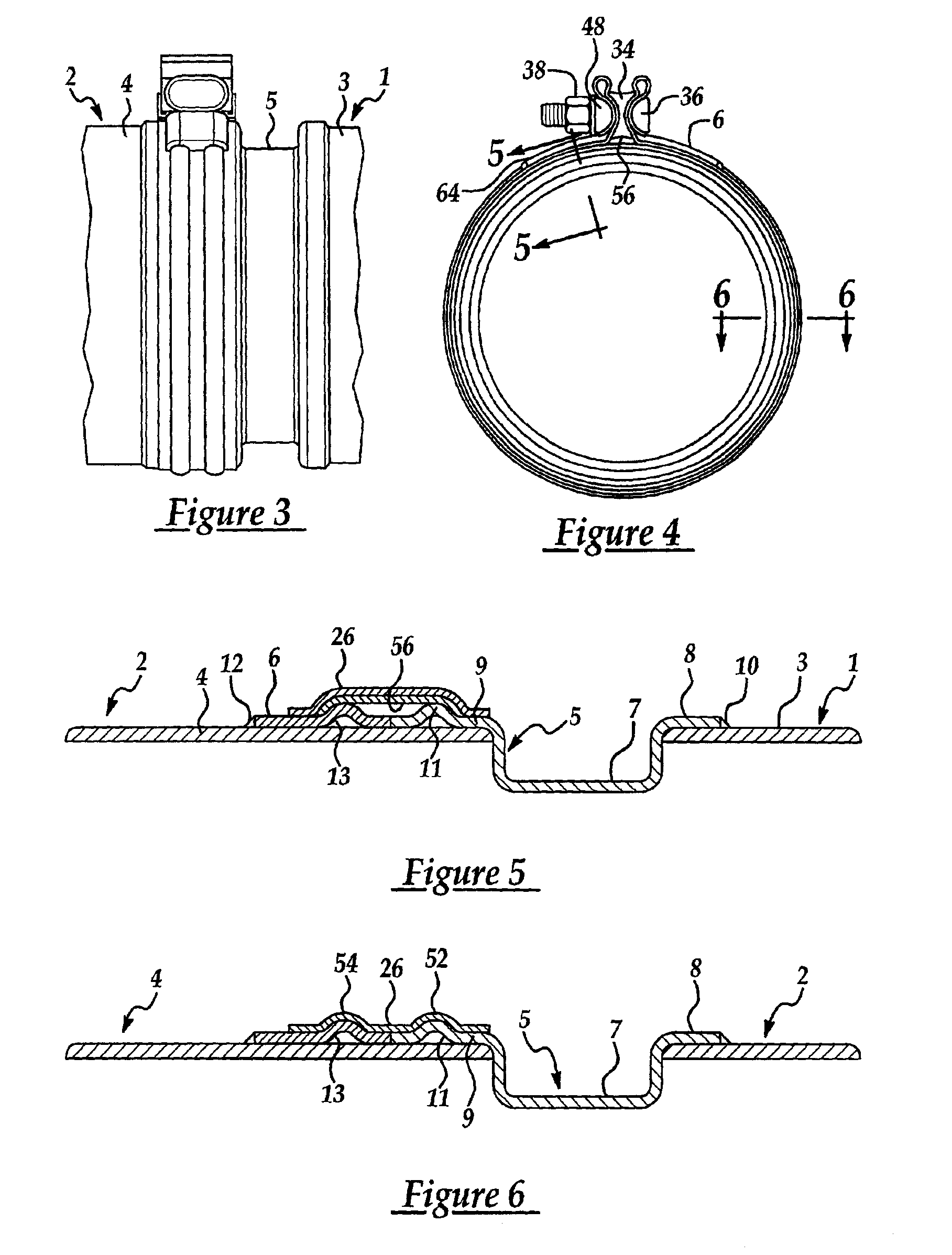
The first embodiment of the band clamp and clamping assembly of this invention will be described with reference to FIGS. 1-6. The band clamp 20 comprises, in general, a clamp band 22 and a clamp tightening mechanism 24. The band 22 comprises a clamp sleeve 26 that is formed as a roundish-shaped sector which defines a circumferential loop. The band 22 has first and second ends which in this embodiment are located at a pair of confronting end flanges 28 that extend radially from the band and are unitary therewith. The end flanges 28 serve as parts of the clamp tightening mechanism 24. Each end flange 28 terminates at its outer end in a retainer bight 32 which is formed by folding the end of the flange on itself to provide a double layer of sheet metal. These folded end flanges 28 comprise clamping members that, when drawn together, pull the first and second ends of the band toward each other to thereby tighten the band clamp.

The clamp tightening mechanism 24 comprises...

second embodiment

of this Invention

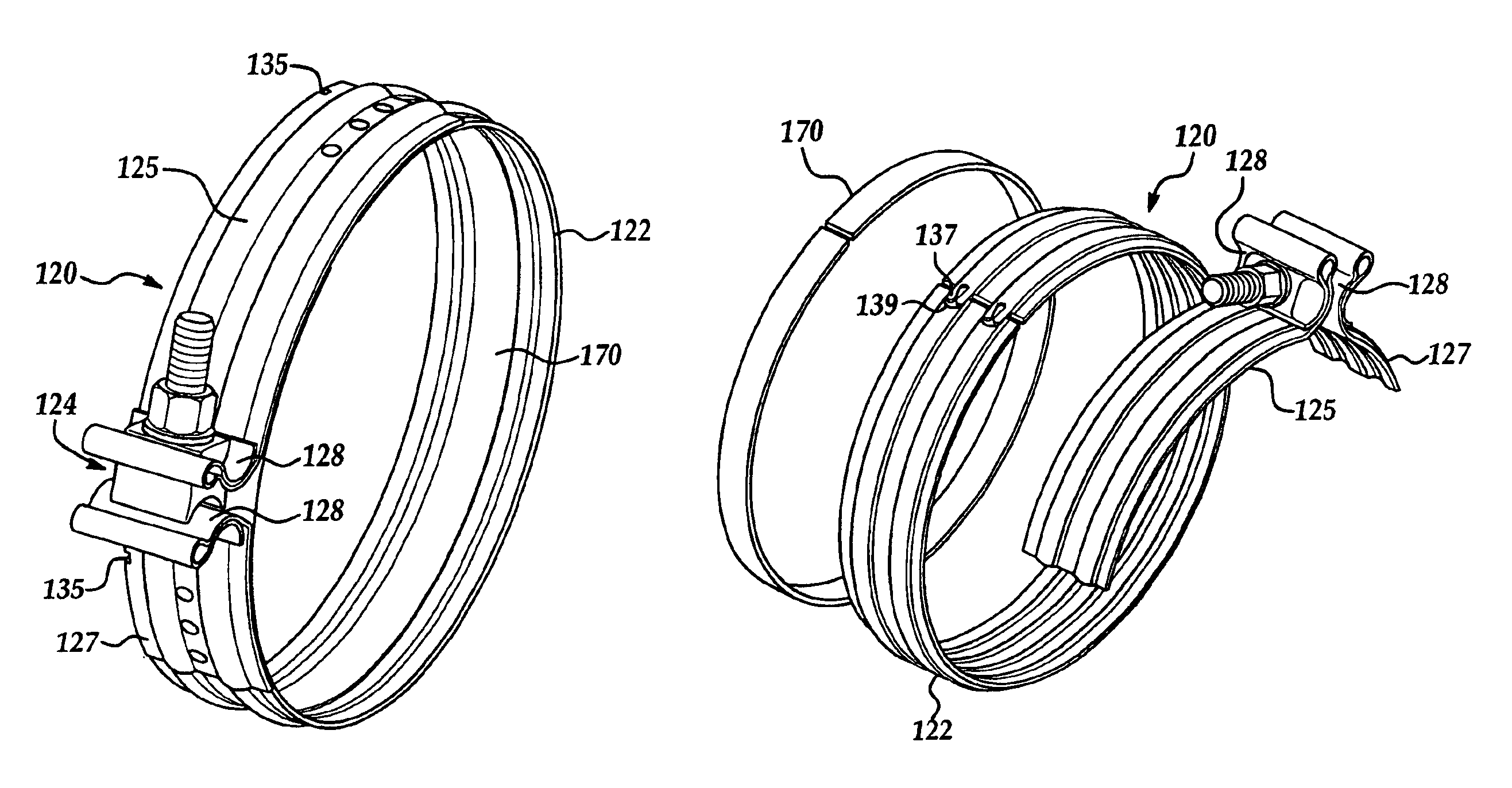
Turning now to FIGS. 15-17, a second embodiment of a band clamp of this invention is shown which can be used in conjunction with the adapters 5 and 6 shown in FIGS. 1-6 or with components having unitary ribs, such as shown in FIGS. 13-14. Elements of this embodiment that correspond functionally to similar elements of the first embodiment are identified with numerals offset by 100 from those used in the first embodiment. Some of these components can be constructed identically to the corresponding components from the first embodiment such as, for example, the tightening mechanism.

Thus, band clamp 120 of FIGS. 15-17 include a band 122 and tightening mechanism 124. Whereas the clamp members 28 of the first embodiment are unitary extensions of the band 22 itself, the clamp members 128 of this second embodiment are formed as confronting portions of a pair of strap sections 125 and 127 that are attached to band 122 by three spot welds each. This enables band 122 to form a ...

third embodiment

of this Invention

The third embodiment of this invention can be implemented the same as in the first or second embodiments except for the structure of the annular ribs. In the third embodiment shown in FIG. 18, the ribs 190 on the band 192 of the band clamp 194 are concave in cross-section with reference to the outer surface of the clamp sleeve instead of being convex as in the first two embodiments. Likewise, the annular ribs on the components being joined (such as the catalytic converter and particulate filter) are concave with respect to the outer surface. Otherwise the structure of the clamp band is the same as that of the first two embodiments of this invention.

The first three embodiments discussed above have involved the joining of tubular bodies or adapters having abutting ends. As shown in FIGS. 19-22, the band clamp of this invention can be used for lap joints as well. As in the first embodiments, it will be noted that, where a gasket 270 or 280 is used, it is located at the...


PUM


Abstract

A band clamp used to connect tubular bodies such as vehicle exhaust system components. The band clamp has a band extending from a first end to a second end and includes a pair of spaced ribs extending at least part way between the first and second ends. A tightening mechanism is connected to the band and includes two clamp members movable toward and away from each other for tightening and loosening of the band. The band clamp further includes a gasket located on an inner surface of the band between the ribs and extending between the first and second ends. The use of the ribs with the interposed gasket provides a mechanical interlock of the band clamp with the tubular bodies while providing a hermetic seal at the junction between the two bodies.

Description

TECHNICAL FIELDThis invention relates to band clamps and more particularly it relates to band clamps for joining tubular bodies.BACKGROUND OF THE INVENTIONThere are many applications in industry which require the joining of two tubular bodies such as pipes, canisters and the like for containing fluid under pressure. Many of these applications require a joint which can be readily opened or disassembled for purposes of maintenance or repair. An example is that of vehicle engine exhaust systems wherein several different exhaust system components such as mufflers, catalytic converters, particulate filters and pipes are coupled together for discharging the exhaust gases to the atmosphere. In exhaust systems, the typical components are round or roundish in cross-section and the joints must provide a good fluid seal against exhaust gas leakage. Also, the joints must exhibit a high degree of mechanical strength for withstanding road shock and vibration without loosening and without impairme...

Claims


Application Information

Patent Timeline
Patent Type & Authority Patents(United States)
IPC IPC(8): F16L21/06F16L21/00
CPCF16L21/005F16L21/065F01N2450/00F01N13/1805
Inventor POTTS, MICHAEL R.IGNACZAK, BRIAN T.AMEDURE, MICHAEL E.
Owner BREEZE TORCA PRODS
Why Eureka
Try Eureka