Method and apparatus for reducing drag of blunt shaped vehicles

Inactive Publication Date: 2005-04-12
CORY GEORGE J
View PDF13 Cites 80 Cited by
  • Summary
  • Abstract
  • Description
  • Claims
  • Application Information

AI Technical Summary

Benefits of technology

In accordance with yet another aspect of the invention, a second vacuum plate having multiple openings may be attached to the vacuum plate at a predetermined distance from the vacuum plate so that an opening or space is maintained between the two vacuum plates. The openings in the vacuum plates may vary in size, shape, and configuration. Further, in an effort to provide an apparatus for reducing drag that can be easily attached and detached from a vehicle, a solid plate member having means for receiving the vacuum plate at a predetermined distance may be attached, either permanently or removably, to the back of the vehicle. In addition, the vacuum plates may be removably or permanently attached to one another at a spaced apart distance thereby allowing them to be attached to the back of the vehicle as one unit or as separate sheets for use either in combination or one at a time.
In accordance with still a further aspect of the invention, additional cover members may be attached to the front portion of a vehicle depending on the type and configuration of the vehicle. For example, a method and apparatus for reducing the drag of a semi-truck trailer may further include a sec

Problems solved by technology

Typical drag reducing devices fail to employ a method to direct the air throug

Method used


Image

  • Method and apparatus for reducing drag of blunt shaped vehicles
  • Method and apparatus for reducing drag of blunt shaped vehicles
  • Method and apparatus for reducing drag of blunt shaped vehicles

Examples


Example

The following descriptions are of exemplary embodiments of the invention only, and are not intended to limit the scope, applicability or configuration of the invention in any way. Rather, the following description is intended to provide a convenient illustration for implementing various embodiments of the invention. As will become apparent, various changes may be made in the function and arrangement of the elements described herein without departing from the spirit and scope of the invention. For example, though not specifically described, many shapes and orientations of the cover piece or cowling, the separation panels, the tubular members, the vacuum plate, and the openings in the vacuum plate, and alternative mechanisms for attaching the cover pieces and vacuum plates to a vehicle should be understood to fall within the scope of the present invention.

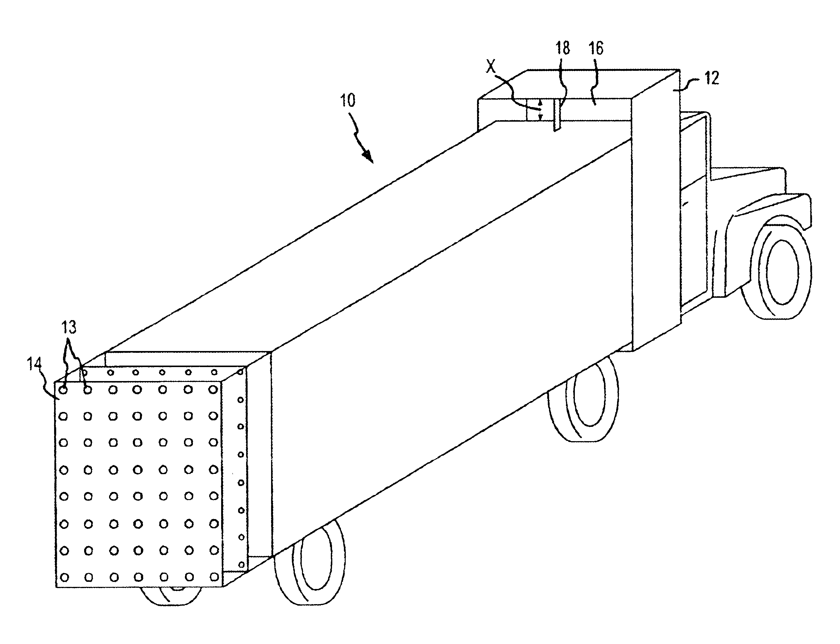
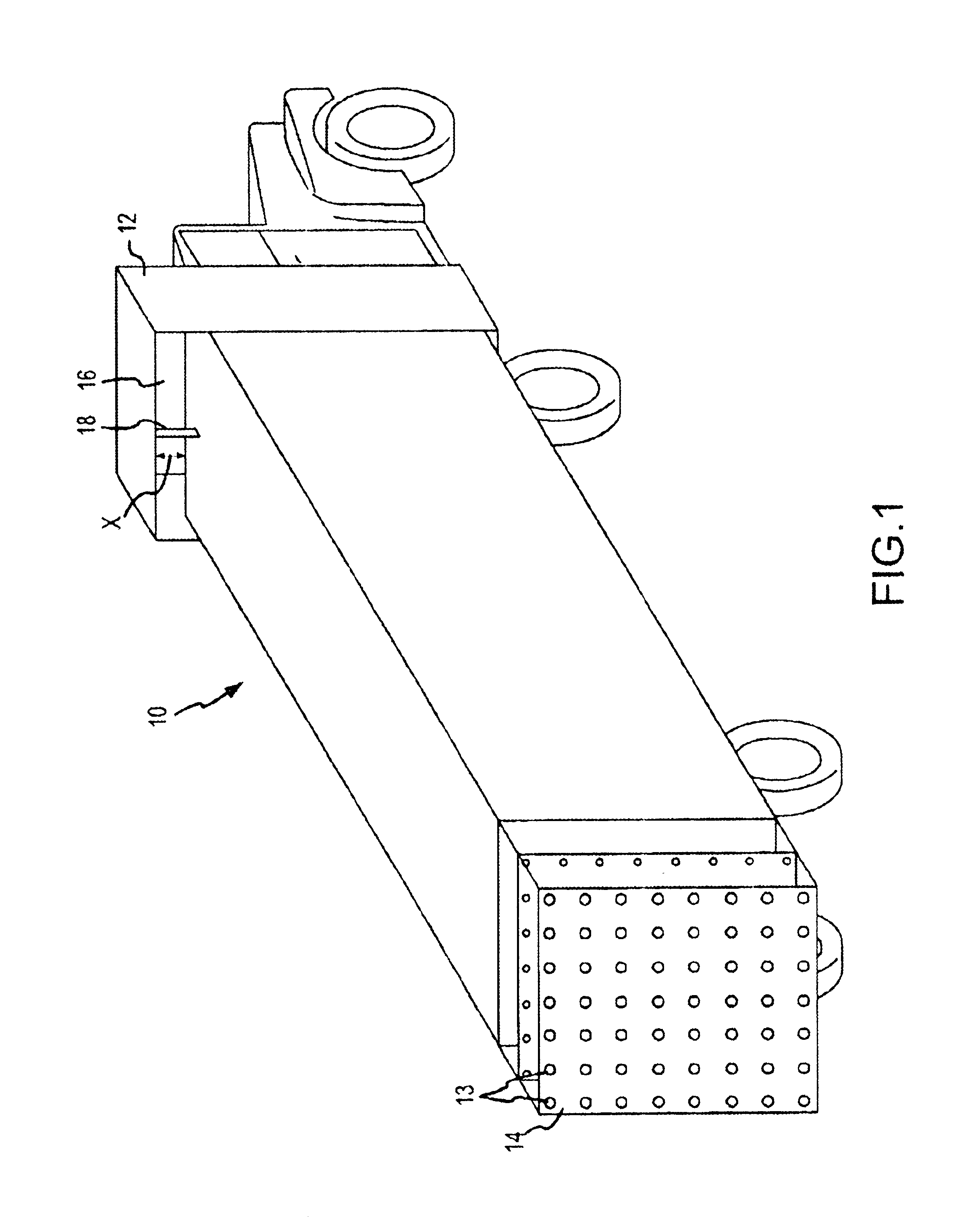
A perspective view of an exemplary embodiment of the drag reducing apparatus 10 of the present invention is shown attached to a veh...


PUM


Abstract

A method and apparatus for reducing the drag of a motor vehicle includes a mechanism for diverting air attached to a front portion of the vehicle and a vacuum plate having openings therein for attachment to a back of the vehicle. Mechanisms for diverting air include a cover piece encasing a front portion of the vehicle, one or more separation panels attached to the front of the vehicle, and one or more tubular members attached to the front of the vehicle. Both the cover piece and vacuum plate are attached to the vehicle so that a space is maintained between the vehicle and the cover piece and vacuum plate, respectively.

Description

FIELD OF INVENTIONThe present invention generally relates to a method and apparatus for reducing the drag, and thereby the operating costs, of blunt shaped vehicles, and more particularly, to a method and apparatus which reduces or collapses the partial or complete vacuum that forms at the front edges and back of blunt vehicles as they move through an air block.BACKGROUND OF THE INVENTIONEfforts to reduce the drag of a radial airplane engine by enclosing it in a cowling has been known in the art for some time. Further, efforts to reduce the drag of other types of motor vehicles such as cars and trucks have also been known in the art for some time. However, typical drag reducing devices for vehicles involve panels of some kind which are generally used to change the shape of the vehicle while it is in motion or when it exceeds a predetermined speed.Typical drag reducing devices fail to employ a method to direct the air through a small space in order to manipulate the pressure of the a...

Claims


Application Information

Patent Timeline
IPC IPC(8): B62D35/00
CPCB62D35/001
Inventor CORY, GEORGE J.
Owner CORY GEORGE J
Why Eureka
Try Eureka