Adjustable armrest

a technology of armrests and adjustable seats, which is applied in the direction of rocking chairs, movable seats, chairs, etc., can solve the problems of various limitations of chairs using these types of springs, and uncomfortable shirt pulling of users, etc., to achieve easy and simple adjustment, improve the tilt control mechanism, and reduce the effect of fatigu

Inactive Publication Date: 2005-04-12
HERMAN MILLER INC
View PDF36 Cites 11 Cited by
  • Summary
  • Abstract
  • Description
  • Claims
  • Application Information

AI Technical Summary

Benefits of technology

In one aspect of the invention, the chair includes a housing, a back support pivotally connected to the housing about a first horizontal axis and a seat support pivotally connected the housing about a second horizontal axis. A leaf spring includes a first end engaging a forward portion of the housing and a second end biasing the seat support and the back support in an upward direction. A fulcrum member is moveably supported in the housing and engages the leaf spring between its first and second end. In operation, the fulcrum member can be easily moved longitudinally within the housing so as to vary the length of the leaf spring lever arm and thereby vary the amount of resistive force supporting the user.
The present invention provides significant advantages over other synchrotilt chairs, and chairs having adjustable backrests and armrests. For example, in the most preferred embodiment, an improved tilt control mechanism is provided which can be manufactured in a compact and aesthetically pleasing housing. In particular, the leaf spring, or preferably a pair thereof, extends longitudinally within the housing, which can be made in a compact and aesthetically pleasing form with little or no depth due to the nature of the spring. The width of the housing also need not be dictated by length of the spring. The resistive force of the leaf springs is easily and simply adjusted by moving the fulcrum member longitudinally within the housing. Consequently, the springs are not prestressed at differing levels, and the adjustment member can be easily manipulated without progressive difficulty. The leaf spring also provides a relatively uniform spring rate throughout the tilting range of the chair.
The leaf springs also are preferably made of composite material, which is more resistant to creep. The leaf spring preferably supports a shaft pivotally connecting the seat support and back support. In this way, the leaf spring biases both members upwardly together, rather than acting on one member with the force then transmitted to the other member through a pivotal attachment. As such, the number of load bearing elements are reduced and simplified.
The three bar slide mechanism also provides several advantages. For example, the linkage provides for a synchrotilt chair wherein the back tilts at a greater rate than the seat, but avoids the use of a fourth bar, which can add to the complexity and manufacturing costs of the chair. Indeed, the overall design is greatly simplified by forming “bars” out of the housing, seat support and back support. Additionally, the use of a slide member allows for the assembly to be made in a more compact and aesthetically pleasing form.
The unique back support also provides many advantages. For example, by providing a one-piece back support, a simplified and aesthetically pleasing structure is provided, which also performs the combined tasks of forming one of the bars of the linkage assembly, providing a support for the backrest and providing a support for the armrests. Additionally, the exoskeletal nature of the back support framing a cushion gives the user a strong visual of support, security and durability. Moreover, by providing uprights along the sides of the chair, the backrest is not required to be structural in nature, and the loads imparted by a user against the side of the backrest can be transmitted directly through the forwardly extending arms of the back support to the housing and spring member so as to provide a more “lively” control for the user. Moreover, since the backrest is supported on both sides, looser tolerances can be accommodated during the assembly of the backrest without sacrificing any tightness in the feel of the backrest.
The uprights can also be used to also support the armrests, which thereby avoids the need for separate supports and complex mechanisms. In this regard, the bar members, which are mounted to the uprights, provide a simple but sturdy support for the backrest and armrests.

Problems solved by technology

In chairs having a backrest pivotally attached to a seat in a conventional manner, the movement of the backrest relative to the seat can create shear forces which act on the legs and back of the user, and which can also create an uncomfortable pulling of the user's shirt, commonly called “shirtpull.”
Chairs using these types of springs can have various limitations associated with the type of spring used therein.
For example, the proper placement of compression springs and / or torsion springs within the chair can often require a large or bulky housing with associated aesthetic limitations.
Moreover, the ride, or resistive force experienced by the user, may be unsatisfactory because spring rates associated with compression springs are not linear and tend to increase as the spring bottoms out.
In addition, the cost of manufacturing the chair, due to the placement of the springs and the introduction of additional load bearing elements, can be increased.
This problem can be exacerbated when two or more springs are used in the chair.
Furthermore, inconsistencies in the performance of compression and torsion springs, and the longevity thereof, can often be traced to the inherent properties of steel, which is typically used to make such springs.
For example, steel is subjected to the problem of “creep” and various inconsistencies introduced during the manufacture of the steel and the subsequent heat-treating processes.
Moreover, because of the requisite size of the springs, the mechanisms used to adjust the amount of initial resistive compression can be difficult to activate, and can be progressively more difficult to adjust as higher settings are reached.
Chairs employing torsion bars may experience similar limitations.
Moreover, as with compression and torsion springs, activation or adjustment mechanisms used to achieve a desired initial pretorque setting can be difficult to manipulate, and can become increasingly so as higher settings are reached.
Holes in the spring can introduce stress risers, however, and clamping one or more ends, as opposed to having them simply supported, introduces indeterminate moments and resultant stresses in the spring which may not be evenly distributed.
As with the other springs described above, such an adjustment mechanism can be difficult to activate, and becomes progressively more so as higher settings are reached.
Moreover, if armrests are desired, they must typically be positioned on separate supports projecting from the seat or from beneath the chair, since the spline centered backrest is usually structurally unable to support the large loads imparted on the armrests by a user along the sides of the backrest.
When adjustable, such armrest supports often house complex and expensive to manufacture height adjustment mechanisms.
As a result, the use of a centered spline can result in a control that feels less “lively” when the occupant is not centered.
Additionally, centered spline chairs often provide an adjustment mechanism adjacent the spline at the center of the back, which can be difficult to access, especially by a seated occupant when the backrest is in a lowermost position.

Method used


Image

  • Adjustable armrest
  • Adjustable armrest
  • Adjustable armrest

Examples


Embodiment Construction

The terms “longitudinal” and “lateral” as used herein are intended to indicate the direction of the chair from front to back and from side to side, respectively. Similarly, the terms “front”, “side”, “back”, “forwardly”, “rearwardly”, “upwardly” and “downwardly” as used herein are intended to indicate the various directions and portions of the chair as normally understood when viewed from the perspective of a user sitting in the chair.

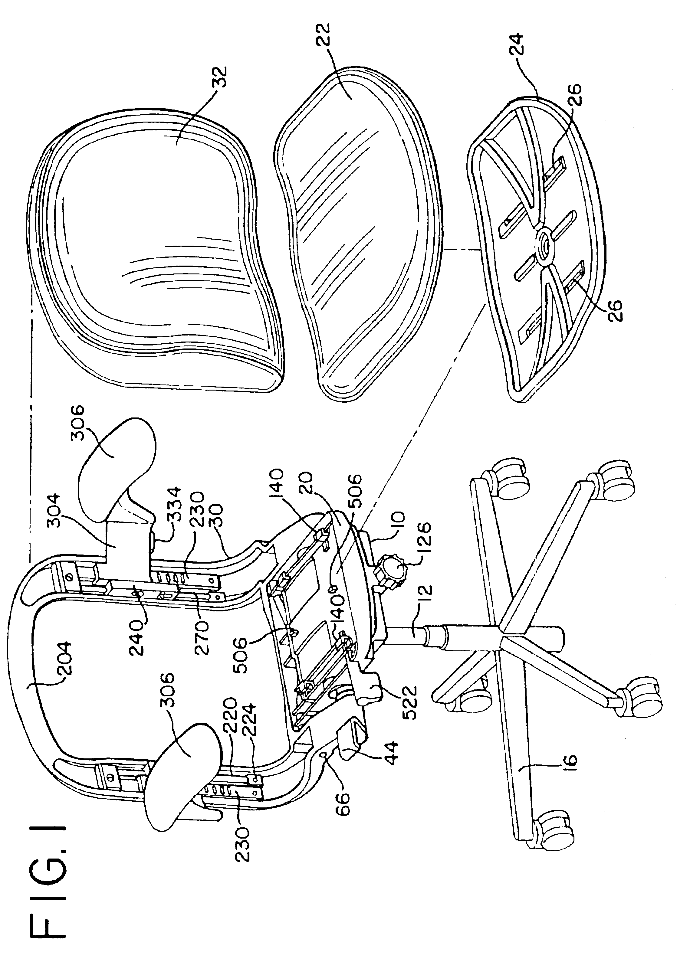
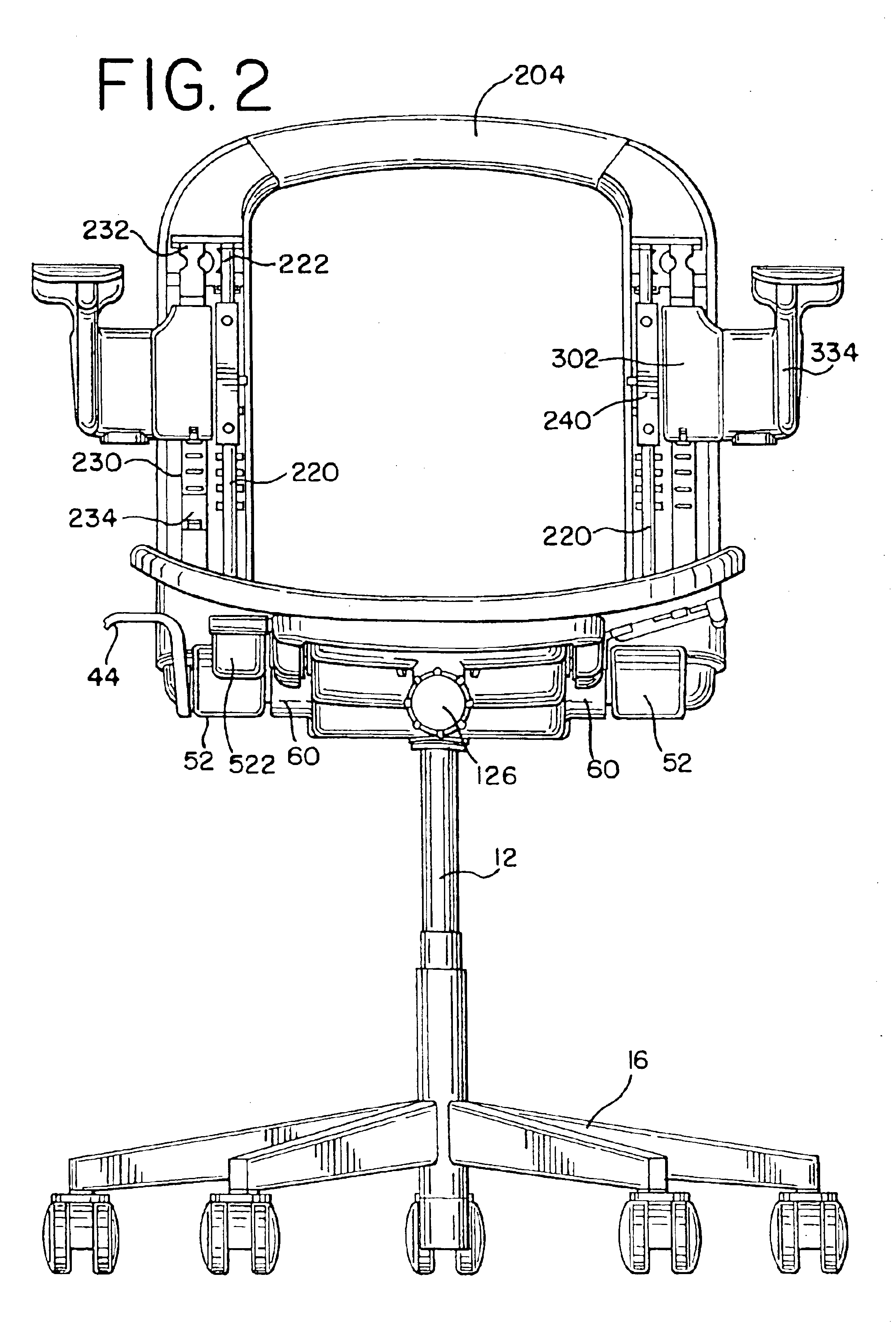
Referring to the drawings, FIG. 1 shows a preferred embodiment of the chair having tilt control housing 10, seat support 20, seat cushion 22, back support 30, backrest 32 and seat pan 24. A pneumatically adjustable support column 12 is mounted to a rear portion of the housing at opening 14 as shown in FIGS. 4 and 6. A top portion of the column 12 having an actuation button extends into the housing. As shown in FIGS. 19-21, a pivot member 34 having a forwardly extending arm 36 engaging a stop 40 and a rearwardly extending arm 38 adapted to engage the ac...


PUM


Abstract

An adjustable armrest for a chair includes a housing having a cavity defined by a wall and a latch member slideably mounted in the cavity. The latch member includes a wedge shaped portion having a first and second surface forming a oblique angle between them. One of the first and second surfaces engages the wall of the housing at least when the latch is in the engaged position.

Description

BACKGROUND OF THE INVENTIONThe present invention relates generally to tiltable chairs, and in particular, to a synchrotilt chair having an adjustable seat, backrest and armrests.Chairs of the type typically used in offices and the like are usually configured to allow tilting of the seat and backrest as a unit, or to permit tilting of the backrest relative to the seat. In chairs having a backrest pivotally attached to a seat in a conventional manner, the movement of the backrest relative to the seat can create shear forces which act on the legs and back of the user, and which can also create an uncomfortable pulling of the user's shirt, commonly called “shirtpull.”To enhance the user's comfort and to promote ergonomically healthy seating, synchro-tilt chairs provide for the seat and backrest to tilt simultaneously, but at different rates, preferably with the back tilting at a greater rate than the seat. Normally, synchro-tilt chairs employ compression and / or tension springs, torsion ...

Claims


Application Information

Patent Timeline
Patent Type & Authority Patents(United States)
IPC IPC(8): A47C7/40A47C1/031A47C1/03A47C1/022A47C1/032A47C3/026A47C3/02
CPCA47C1/03A47C1/03238A47C1/03255A47C7/402A47C1/03277A47C1/03294A47C1/03266A47C1/0303
Inventor CARUSO, JEROME C.CARUSO, STEVEN J.GEZON, BRUCE R.GIERZ, MARC A.NYENHUIS, JACK R.
Owner HERMAN MILLER INC
Why Eureka
Try Eureka