Gas turbine

a gas turbine and turbine blade technology, applied in the direction of machines/engines, stators, liquid fuel engines, etc., can solve the problems of limited aerodynamic loading of fans and compressors of aero engines and stationary gas turbines, unsteady disturbance of flow, and damage to compressors or the entire gas turbine, so as to reduce the number of compressor stages. , the effect of high flow loss

Inactive Publication Date: 2005-04-12
ROLLS ROYCE DEUT LTD & CO KG
View PDF4 Cites 14 Cited by
  • Summary
  • Abstract
  • Description
  • Claims
  • Application Information

AI Technical Summary

Benefits of technology

The design according to the present invention provides for a directionally stabilizing conduction of flow upstream of the respective blade/vane row. Contrarily, the grooves or slots known from the state of the art act as recesses which overlap axially with the respective blade/vane rows and, due to strong interactive effects, entail high flow losses.
Accordingly, the present invention provides for a continual conduction or guidance of the near-wall flow, considerably delaying the formation of stall at the free ends of the rotor blades or stator vanes and generally providing fo

Problems solved by technology

The aerodynamic loading of fans and compressors of aero engines and stationary gas turbines is limited by the requirement of sufficient flow stability.
These two operating states delimit the operating range of the compressor and may result in the compressor or the entire gas turbine being damaged.
These arrangements cause an unsteady disturb

Method used


Image

  • Gas turbine
  • Gas turbine
  • Gas turbine

Examples


Embodiment Construction

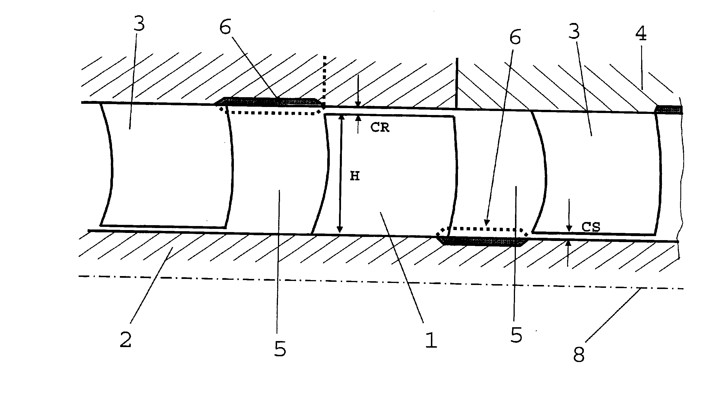
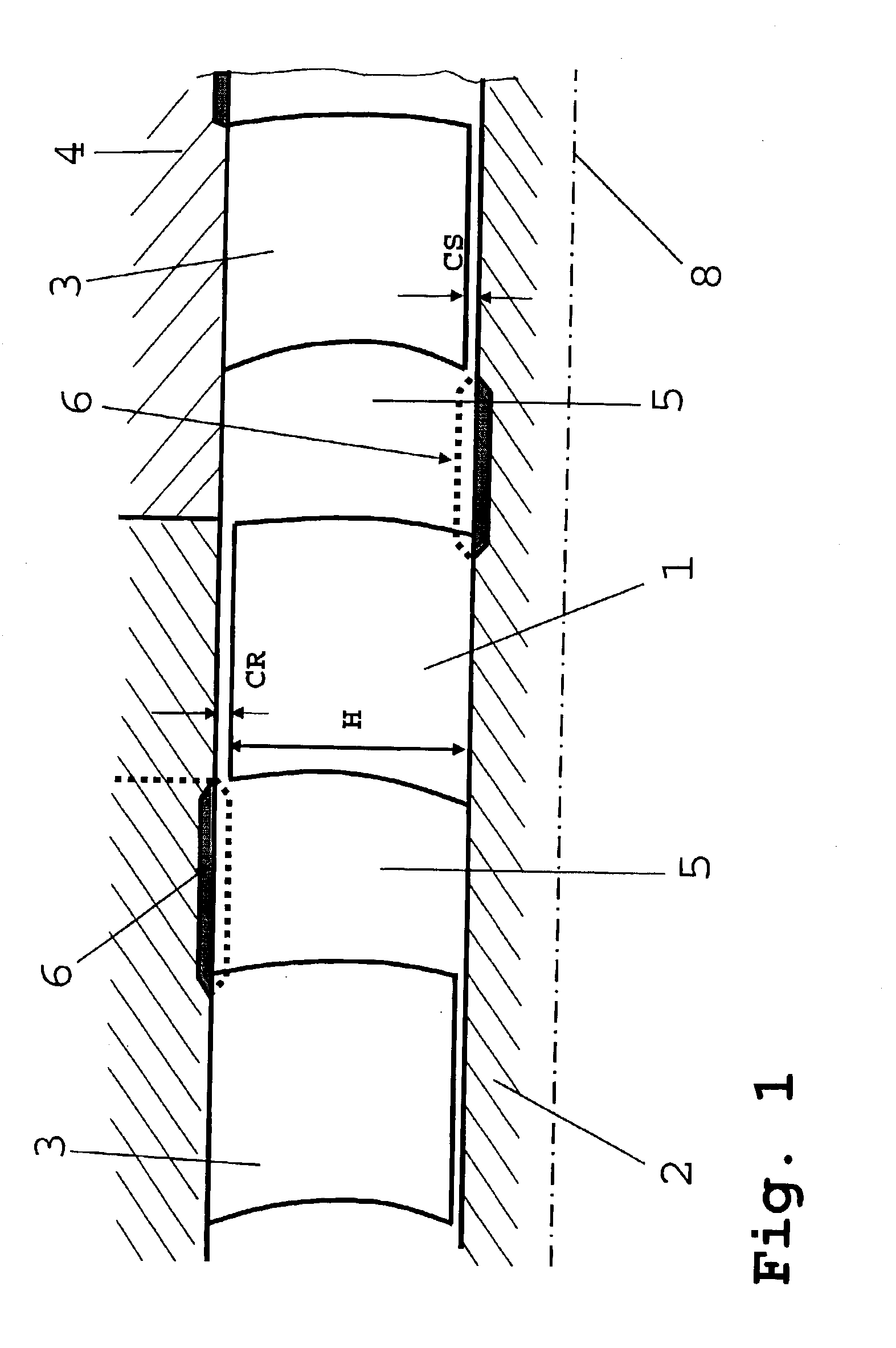
This detailed description should be read in conjunction with the summary of the invention above. FIG. 1 is a schematic side view of a partial area of a compressor area in accordance with the present invention. Reference numeral 8 indicates a rotational axis of the gas turbine around which a rotor shaft 2 is rotatable and to which, in turn, a number of rotor blades 1 are attached. These are surrounded by a casing 4 which carries several arrangements of stator vanes 3.

The free space between the casing 4 and the rotor shaft 2 is marked H. The distance between the free ends of the rotor blades 1 and the casing 4 is marked CR, and the distance between the free ends of the stator vanes 3 and the rotor shaft 2 is marked CS.

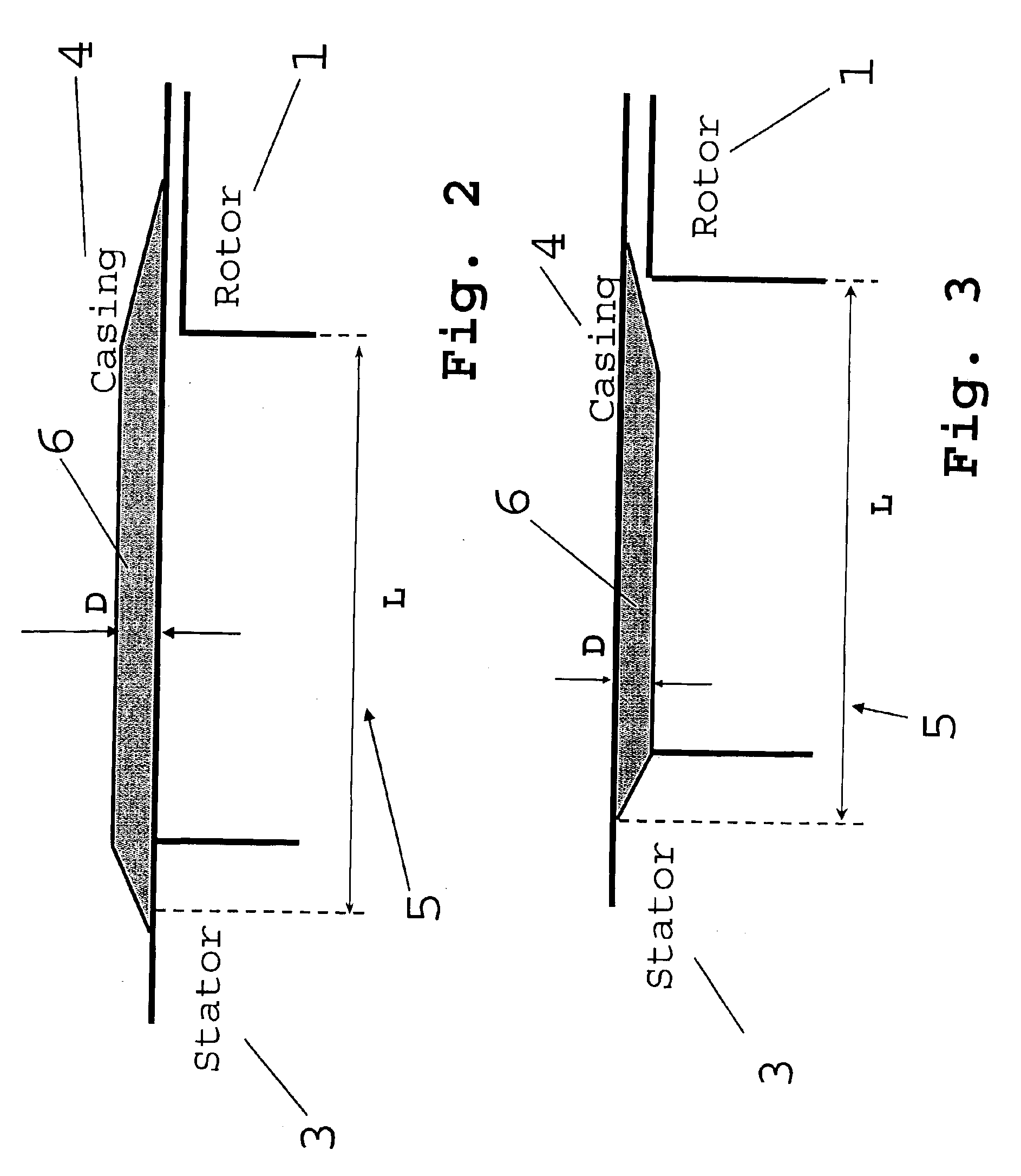
The stator vanes 3 and rotor blades 1 form a clearance space 5 in which a number of fins 6 are provided, these fins being described hereinafter. The fins 6 represented in FIG. 2 can be produced by material removal (for example by milling or a similar process). The height...


PUM


Abstract

A gas turbine with a compressor area has a rotor shaft 2 to carry rotor blades 1 and a casing 4 to carry stator vanes 3, with the related rotor blades 1 and stator vanes 3 forming an axial clearance space 5 between one another, wherein, in the area of the axial clearance space 5, at least one wall of the rotor shaft 2 and/or of the casing 4 is provided with an arrangement of fins 6 which are inclined against the axial direction.

Description

This application claims priority to German Patent Application DE10205363.4 filed Feb. 8, 2002, the entirety of which is incorporated by reference herein.BACKGROUND OF THE INVENTIONThis invention relates to a gas turbine.More particularly, the present invention relates to a gas turbine with a compressor area which has a rotor shaft to carry the rotor blades and a casing to carry stator vanes, with related rotor blades and stator vanes forming an axial clearance space between one another. Within the framework of the present invention the term compressor area shall be read to apply to the portion of either a fan or a compressor.The aerodynamic loading of fans and compressors of aero engines and stationary gas turbines is limited by the requirement of sufficient flow stability. The loading of the individual compressor stages may, however, be increased by taking special measures against flow stall or surge.The present invention relates to the design of the walls of both the rotor shaft a...

Claims


Application Information

Patent Timeline
IPC IPC(8): F04D27/02F01D5/14F04D29/68F04D29/66F04D29/54F04D29/40
CPCF01D5/145F04D27/0207F04D29/547F04D29/681Y10S415/914Y02T50/673F05D2250/28F05D2250/314F04D29/321F04D29/526F04D29/685Y02T50/60
Inventor GUEMMER, VOLKER DR.
Owner ROLLS ROYCE DEUT LTD & CO KG
Why Eureka
Try Eureka