Stent graft loading and deployment device and method

a technology of stent graft and deployment device, which is applied in the field of tubular prosthesis, can solve the problems of high mortality rate and complex surgical procedure, and achieve the effect of small pre-deployment and collapsed profil

Inactive Publication Date: 2005-04-12
MEDTRONIC VASCULAR INC
View PDF9 Cites 142 Cited by
  • Summary
  • Abstract
  • Description
  • Claims
  • Application Information

AI Technical Summary

Benefits of technology

An embodiment according to present invention provides an improved endoluminal prosthesis having a tubular graft with a support structure attached to the tubular graft, configured in a manner that provides device flexibility while maintaining a relatively small pre-deployed, collapsed profile.

Problems solved by technology

The surgical procedure is complex and requires long hospital stays due to serious complications and long recovery times and has high mortality rates.
Although frequently referred to as stent-grafts, these devices differ from covered stents in that they are not used to mechanically prop open natural blood vessels.
One challenge in implanting the endoluminal prostheses is to provide delivery catheter access to the site.

Method used


Image

  • Stent graft loading and deployment device and method
  • Stent graft loading and deployment device and method
  • Stent graft loading and deployment device and method

Examples


Embodiment Construction

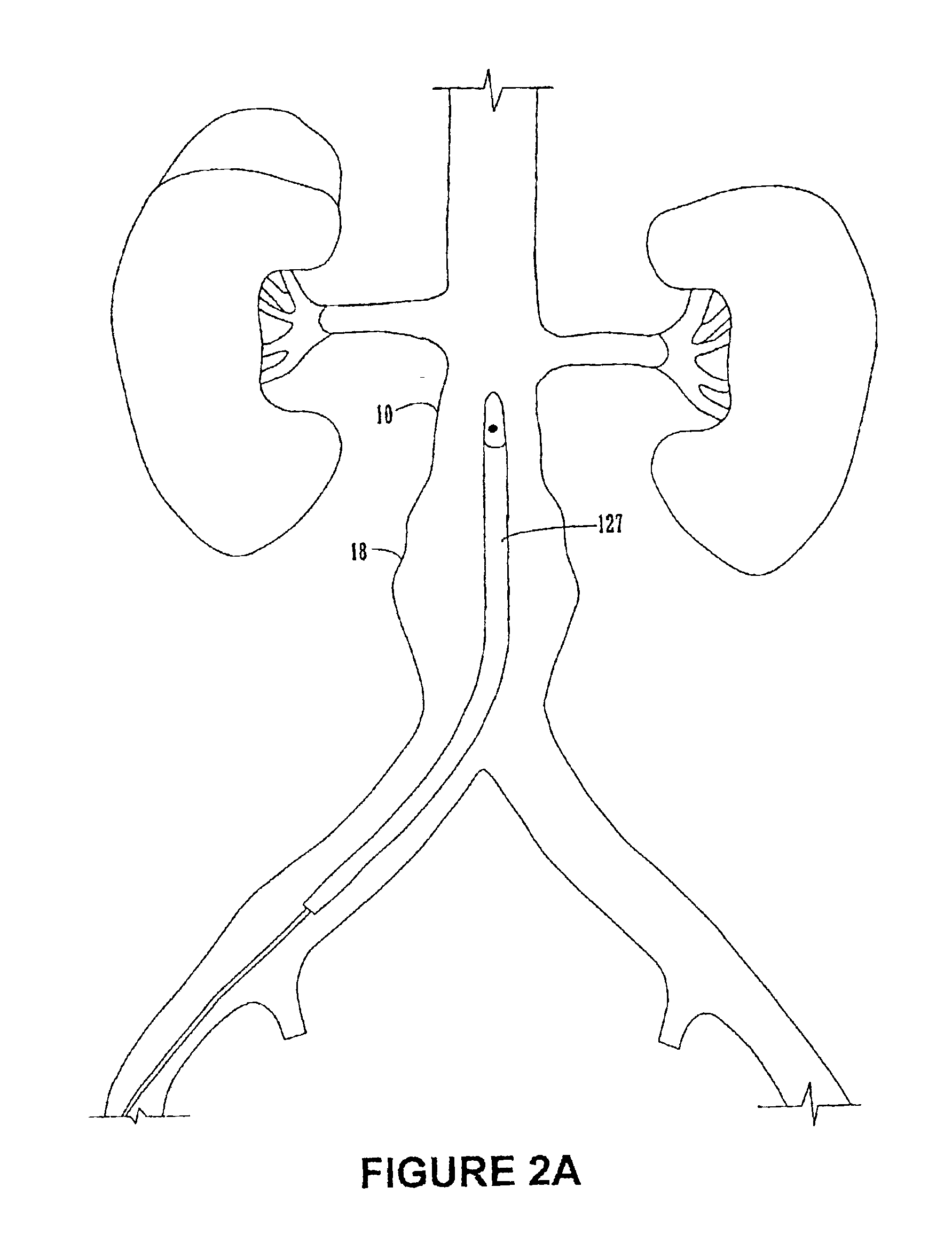
FIGS. 1A-8 illustrate various embodiments of the endoluminal prosthesis, delivery systems and methods according to the present invention. Although an endoluminal prosthesis, delivery system and method according to the invention may be used in any body lumen that conducts body fluid, they are described herein with reference to treatment of an aortic aneurysm, in particular in the abdomen of a patient.

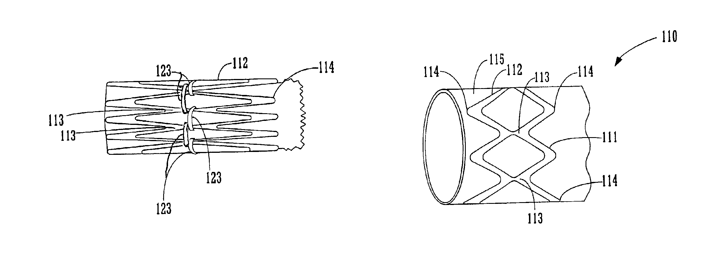
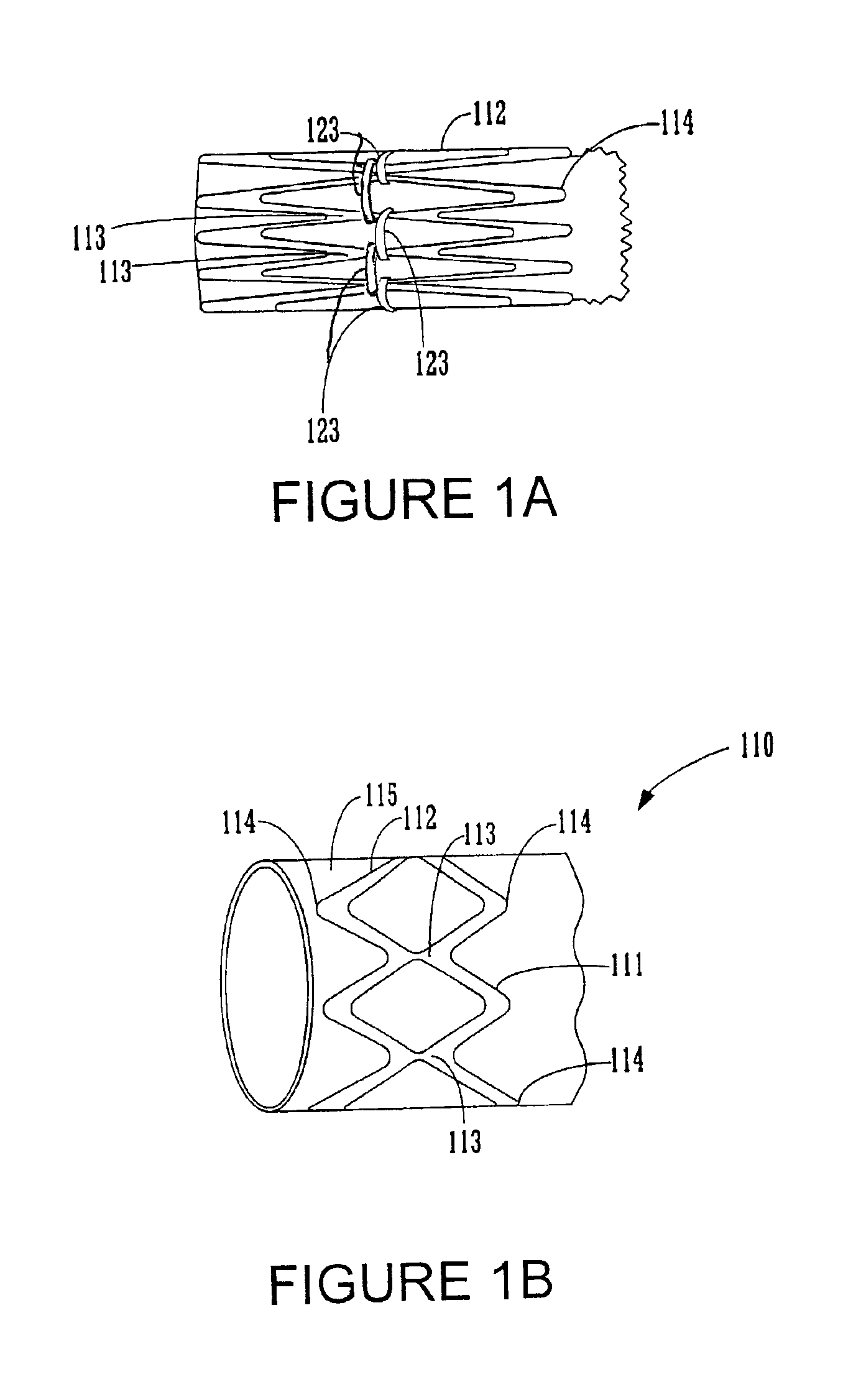
FIGS. 1A and 1B illustrate an embodiment of an endoluminal prosthesis 110. The prosthesis 110 comprises a tubular graft 115 and a series of radially compressible annular support members 112 attached to tubular graft 115. The annular support members 112 support the graft and / or bias the prosthesis 110 into conforming fixed engagement with an interior surface of an aorta 10 (See FIG. 2C). The annular support members 112 are preferably spring members having a predetermined radii and are preferably constructed of a material such as Nitinol in a superelastic, shape set, annealed condition

The ...


PUM


Abstract

An endoluminal prosthesis includes a tubular graft, an expandable annular support structure and a restraining mechanism restraining the prosthesis in a collapsed configuration in which the annular support structure is compressed to a low profile. The restraining mechanism holds the annular support structures in the collapsed configuration until the prosthesis is positioned for deployment. The restraining mechanism is then released to allow the annular support structures to expand into conforming engagement with the inner wall of a lumen in which the prosthesis is to be deployed. A feature according to the invention provides a balloon catheter onto which the prosthesis is loaded for deployment where the balloon is expanded to provide a radial force to release the restraining mechanism. Another feature provides for a restraining member that breaks upon application of the radial force to release the annular support structure from its constrained configuration. Another feature of the invention provides for independent and/or sequential release of the annular support members. Various types of annular support members attached to tubular grafts in a variety of manners may be used in accordance with the invention. The invention may be used in tubular grafts for endoluminal placement within a body lumen, including blood vessels, and for the treatment of abdominal and other aneurysms.

Description

FIELD OF THE INVENTIONThe present invention relates to tubular prostheses such as grafts and endoluminal prostheses including, for example, stent-grafts and aneurysm exclusion devices, and methods for placement of such grafts and endoluminal structures. Further, the present invention relates to a stent graft deployment device and method.BACKGROUND OF THE INVENTIONA wide range of medical treatments have been previously developed using “endoluminal prostheses,” which terms are herein intended to mean medical devices which are adapted for temporary or permanent implantation within a body lumen, including both naturally occurring or artificially made lumens. Examples of lumens in which endoluminal prostheses may be implanted include, without limitation: arteries such as those located within coronary, mesentery, peripheral, or cerebral vasculature; veins; gastrointestinal tract; biliary tract; urethra; trachea; hepatic shunts; and fallopian tubes. Various types of endoluminal prostheses ...

Claims


Application Information

Patent Timeline
Patent Type & Authority Patents(United States)
IPC IPC(8): A61F2/06A61F2/90
CPCA61F2/07A61F2/90A61F2/844A61F2002/075A61F2002/9511A61F2220/0075A61F2230/0054A61F2230/0067A61F2220/005A61F2220/0066A61F2/89
Inventor LENKER, JAY A.
Owner MEDTRONIC VASCULAR INC
Why Eureka
Try Eureka