
Resonance shifting

a technology of resonant shifting and vibrator, which is applied in piezoelectric/electrostrictive/magnetostrictive devices, piezoelectric/electrostriction/magnetostriction machines, electrical apparatus, etc., can solve the problems of not being able or practic and not being able to determine the dimensions of the vibrator

Inactive Publication Date: 2005-04-12
NANOMOTION
View PDF17 Cites 19 Cited by
  • Summary
  • Abstract
  • Description
  • Claims
  • Application Information

AI Technical Summary

Benefits of technology

An aspect of some preferred embodiments of the present invention relates to providing a method for shifting resonant frequencies of vibration modes of a piezoelectric vibrator without substantially changing overall dimensions of the piezoelectric vibrator.
There is further provided, in accordance with a preferred embodiment of the present invention, a method for reducing a tendency for a piezoelectric vibrator to fracture in a neighborhood of a cavity defined by a cavity wall on a surface of the vibrator or in the body of the vibrator comprising determining an elastic material that bonds to the material from which the piezoelectric vibrator is formed; and bonding the elastic material to the cavity wall.

Problems solved by technology

As a result of the many operational parameters of a piezoelectric vibrator that are functions of the vibrator's dimensions, it is generally not possible to determine dimensions of a vibrator that optimize all operational characteristics of the vibrator.
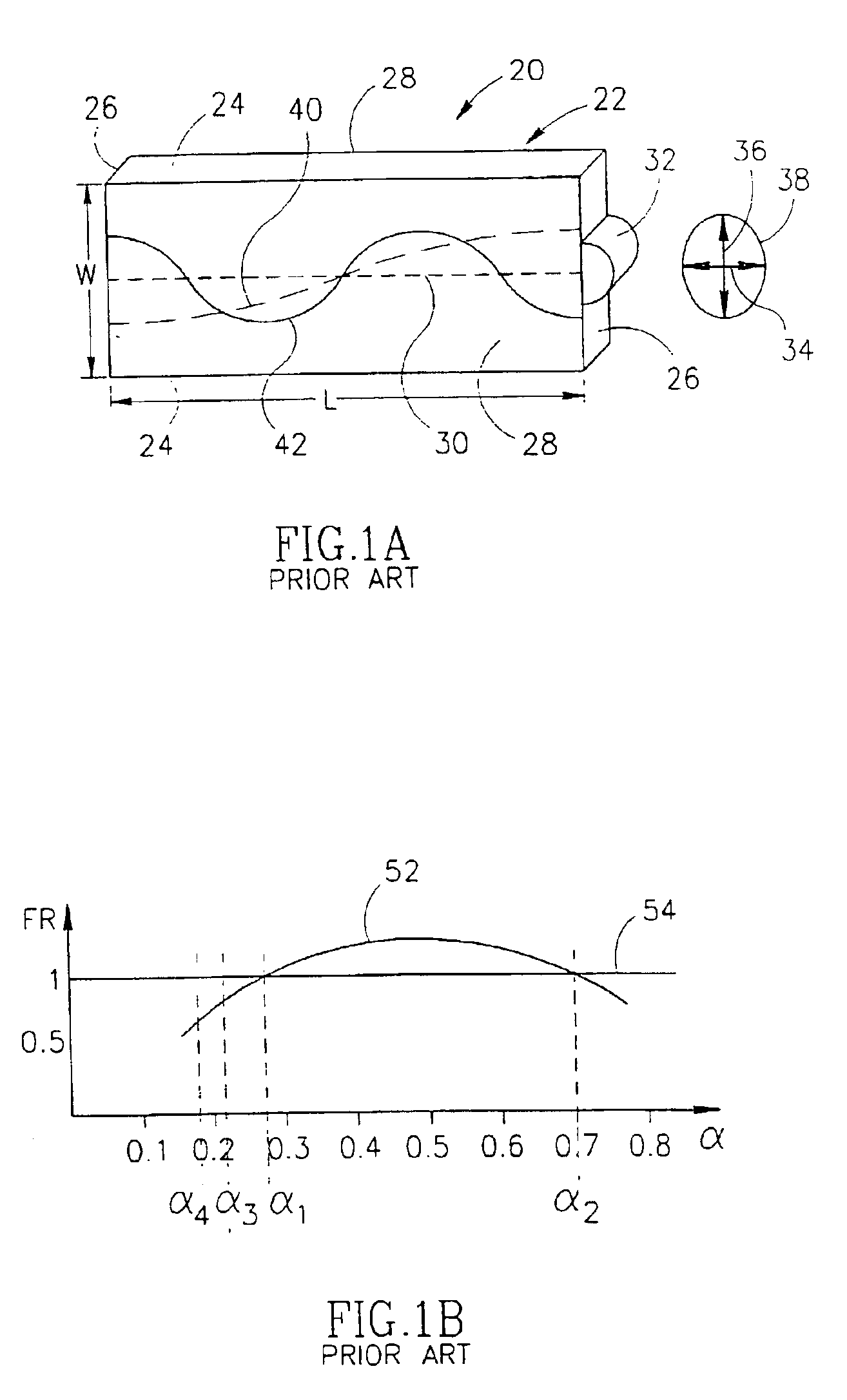
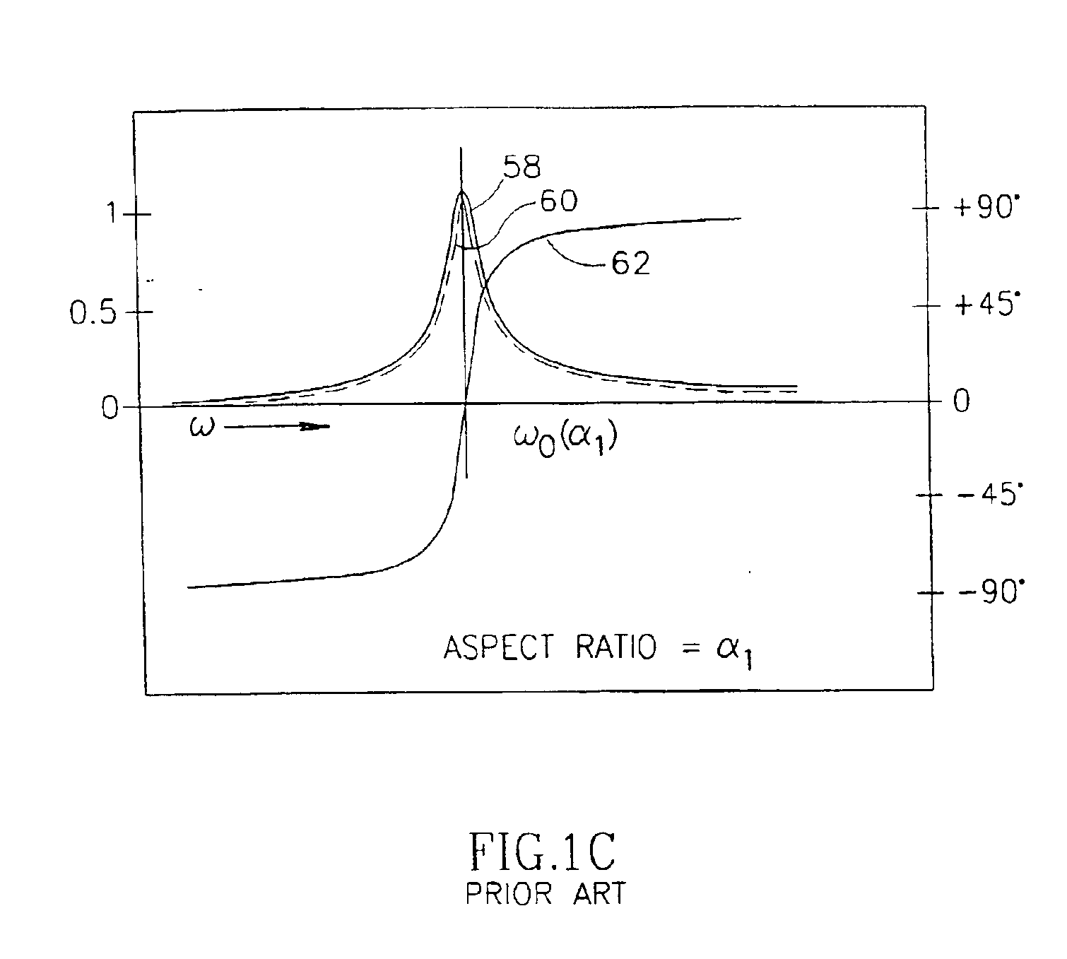
In particular, it is not always possible or practical to determine dimensions of a vibrator so that excitation curves of a perpendicular and a parallel vibration mode overlap at a frequency at which both vibration modes can be efficiently excited with a 90° mode phase difference.

Method used


Image

  • Resonance shifting
  • Resonance shifting
  • Resonance shifting

Examples


Embodiment Construction

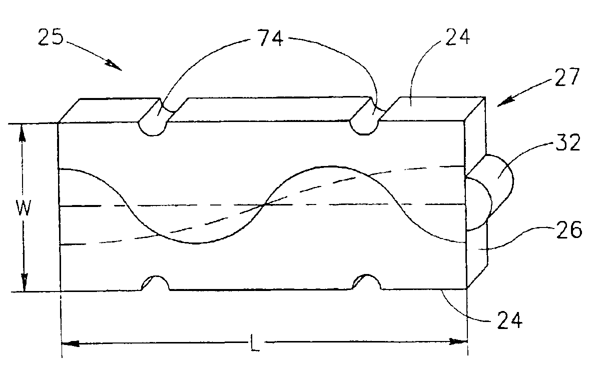
FIG. 1A schematically shows a piezoelectric motor 20 of a type described in U.S. Pat. No. 5,453,653 to Zumeris et al, the disclosure of which is incorporated herein by reference. Piezoelectric motor 20 comprises a thin rectangular piezoelectric vibrator 27 having long edge surfaces 24 and short edge surfaces 26 and large parallel face surfaces 28. The length of long edge surfaces 22 and the length of short edge surfaces 26 (i.e. the width of vibrator 22) are noted as “L” and “W” respectively. A long axis 30 of piezoelectric motor 20, shown with a dashed line, passes through the center of vibrator 22 parallel to long edge surfaces 24. Various surface regions of piezoelectric motor 20 may be used for a motor-coupling-surface and some piezoelectric motors similar to piezoelectric motor 20 have more than one motor-coupling-surface. Generally, a region of a short edge surface 26 or a surface of a friction nub located on a short edge surface 26 functions as a motor-coupling-surface. In FI...


PUM


Abstract

A piezoelectric vibrator comprising: a thin rectangular piezoelectric plate formed of a material having a Young's modulus having to short edges surfaces and two long edge surfaces and two long planar face surfaces which plate has transverse resonant vibration modes parallel to its short edges and longitudinal resonant vibration parallel to its long edges and is formed with at least one cavity; and least one electrode on each of the planar surfaces that is electrifiabie to excite at least one vibration mode of the plate, wherein the at least one cavity is not filled with a material having a Young's modulus substantially equal to the Young's modulus of the material from which the place is formed, such that the presence of the at least one cavity shifts a resonant frequency of at least one vibration mode of the plate with respect to the resonant frequency that characterizes the at least one vibration mode in the absence of the at least one cavity.

Description

FIELD OF THE INVENTIONThe invention relates to piezoelectric motors and in particular to methods for shifting the frequencies of resonant vibrations of piezoelectric motors.BACKGROUND OF THE INVENTIONA piezoelectric motor uses a piezoelectric vibrator to transduce electrical energy into kinetic energy that the motor transmits to a moveable body to which the motor is coupled. The motor is generally coupled to a body that it moves by resiliently pressing the motor to the body so that a surface region, hereinafter referred to as a “motor-coupling-surface”, of its piezoelectric vibrator contacts a surface, hereinafter referred to as a “body-coupling-surface”, of the body. Electrodes comprised in the motor are electrified (generally with an AC voltage) to excite vibrations in the vibrator that cause the motor-coupling-surface to vibrate. Motion is transmitted from the vibrating motor-coupling-surface to move the body by frictional forces between the motor-coupling-surface and the body-co...

Claims


Application Information

Patent Timeline
Patent Type & Authority Patents(United States)
IPC IPC(8): H01L41/09H02N2/12H10N30/00H10N30/20
CPCH01L41/253H01L41/0906H10N30/2023H10N30/04
Inventor SHIV, LIORRAFAELI, IZHOKGANOR, ZO'EVKABASIKOV, NIRDODIUK-KENIG, HANNA
Owner NANOMOTION
Learn More