
Surface acoustic wave apparatus and communication apparatus using the same

a surface acoustic wave and apparatus technology, applied in piezoelectric/electrostrictive/magnetostrictive devices, piezoelectric/electrostrictive/magnetostrictive devices, semiconductor devices, etc., can solve problems such as defective connection to the package, and achieve the effect of reducing the parasitic capacitance of the surface acoustic wave apparatus and reducing the insertion loss

Inactive Publication Date: 2005-04-12
MURATA MFG CO LTD
View PDF7 Cites 16 Cited by
  • Summary
  • Abstract
  • Description
  • Claims
  • Application Information

AI Technical Summary

Benefits of technology

To overcome the problems described above, preferred embodiments of the present invention provide a surface acoustic wave apparatus in which the surface acoustic wave resonator 102 is connected in series to the longitudinally-coupled-resonator surface acoustic wave filter 101, as shown in FIG. 3, and which has a greatly decreased insertion loss within the pass band, and which includes a layout that greatly reduces the parasitic capacitance of the surface acoustic wave apparatus on a piezoelectric substrate.
A communication apparatus according to another preferred embodiment of the present invention includes any of the surface acoustic wave apparatuses described above. With this structure, since the communication apparatus includes the surface acoustic wave apparatus having a greatly reduced insertion loss and superior transmission characteristics, the communication apparatus has greatly improved communication characteristics.

Problems solved by technology

The dedicated characteristic selection pads are provided because the electrode pads can be damaged by contact with the tip of the probe when the measurement is performed, thus, causing defective connection to the package.

Method used


Image

  • Surface acoustic wave apparatus and communication apparatus using the same
  • Surface acoustic wave apparatus and communication apparatus using the same
  • Surface acoustic wave apparatus and communication apparatus using the same

Examples


first preferred embodiment

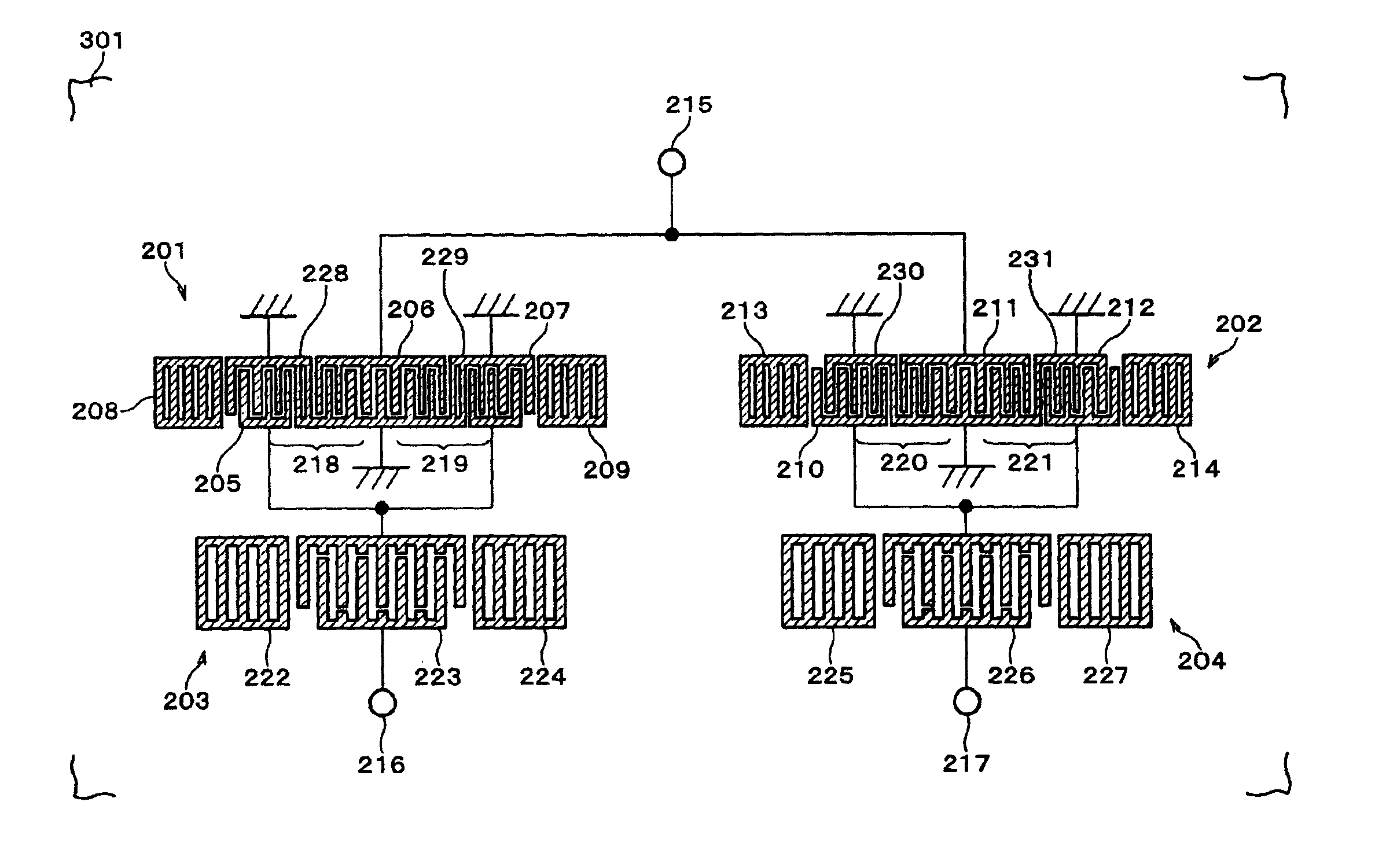
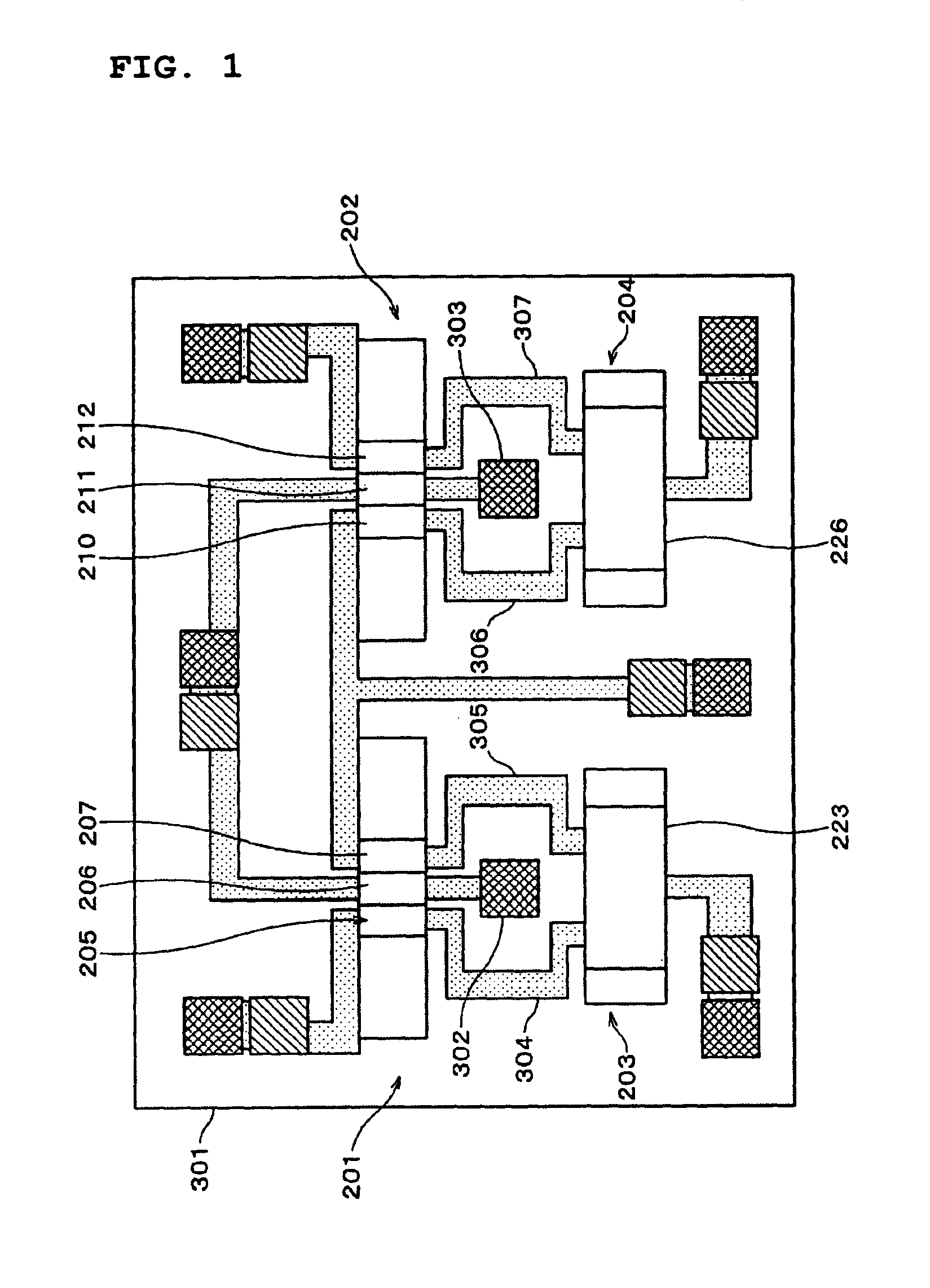
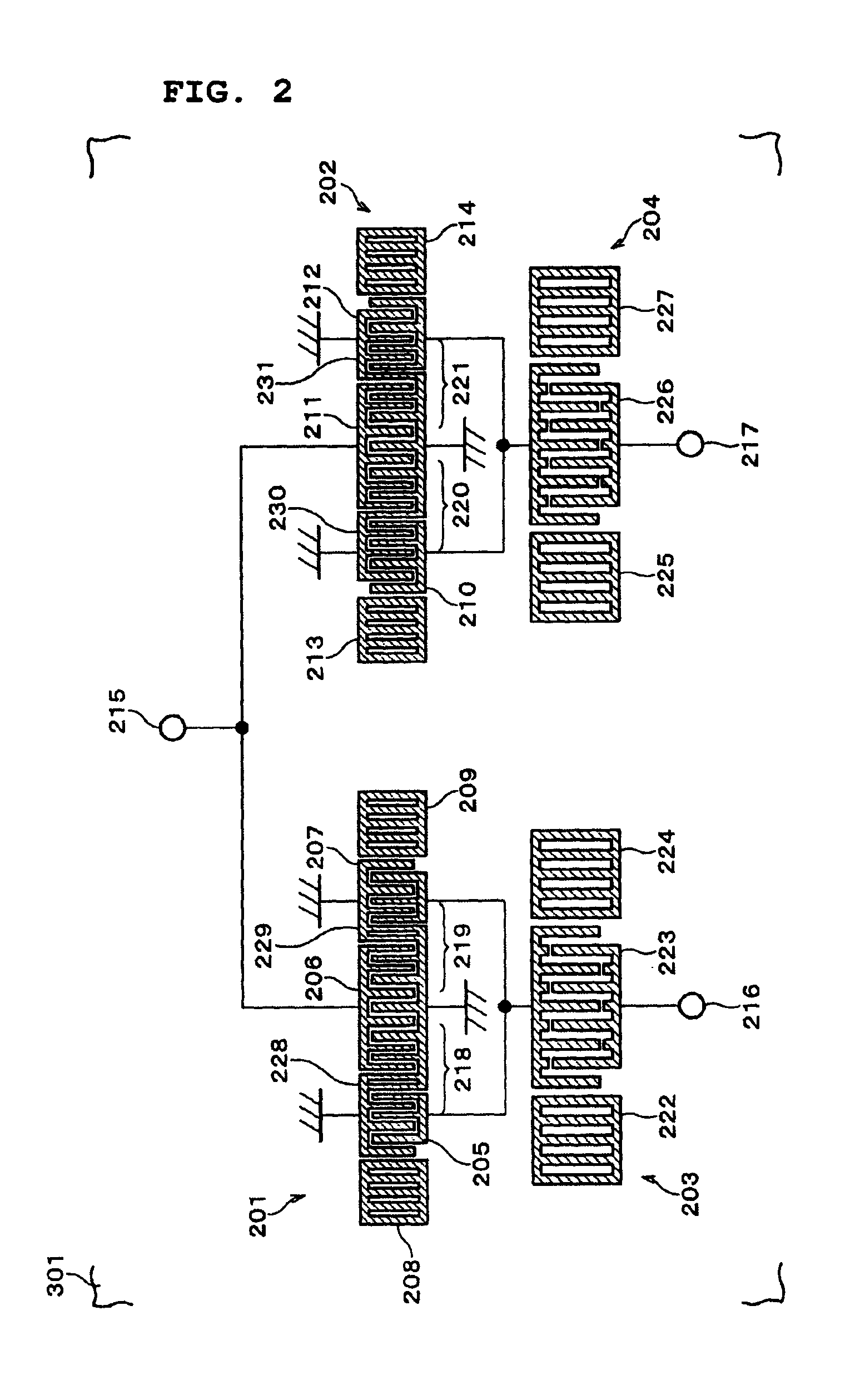
A surface acoustic wave apparatus according to a first preferred embodiment of the present invention will now be described with reference to FIGS. 1, 2, and 5. The preferred embodiments of the present invention will be described in the context of a digital communication system (DCS) reception filter (the center frequency within the pass band is 1842.5 MHz). First, the electrode structure according to the first preferred embodiment will be described with reference to FIG. 2.

Longitudinally-coupled-resonator surface acoustic wave filters 201 and 202 and surface acoustic wave resonators 203 and 204 that are connected in series to the longitudinally-coupled-resonator surface acoustic wave filters 201 and 202, respectively, are provided on a piezoelectric substrate 301 preferably made of X-propagation LiTaO3 that is Y-cut at 40±5°. The longitudinally-coupled-resonator surface acoustic wave filters 201 and 202 and the surface acoustic wave resonators 203 and 204 preferably include aluminum...

second preferred embodiment

A second preferred embodiment of the present invention will now be described with reference to FIGS. 21 and 22. The electrode structure according to the second preferred embodiment will be described with reference to FIG. 21. A longitudinally-coupled-resonator surface acoustic wave filter 1201 and a surface acoustic wave resonator 1202 that is connected in series to the longitudinally-coupled-resonator surface acoustic wave filter 1201 are provided on a piezoelectric substrate 301 that is preferably made of X-propagation LiTaO3 that is Y-cut at 40±5°. The longitudinally-coupled-resonator surface acoustic wave filter 1201 and the surface acoustic wave resonator 1202 preferably include aluminum electrodes.

In the longitudinally-coupled-resonator surface acoustic wave filter 1201, IDTs 1203 to 1207 that are arranged along the propagation direction of the surface acoustic waves are sandwiched between reflectors 1208 and 1209. Referring to FIG. 21, the spacing between the electrode finger...

third preferred embodiment

FIG. 30 shows a third preferred embodiment of the present invention. In the structure in FIG. 30 having a similar structure to that of the first preferred embodiment, the bus bars of IDTs 205c, 206c, 207c, 210c, 211c, and 212c are configured so as to be thinner, than in the other areas, in areas (areas 1501 to 1504 in FIG. 30) where signal electrodes are adjacent to the corresponding ground electrodes and the parasitic capacitance occurs between longitudinally-coupled-resonator surface acoustic wave filters 201c and 202c and the corresponding surface acoustic wave resonators 203 and 204.

In other words, in the bus bars of the IDTs 205c, 206c, 207c, 210c, 211c, and 212c, the spacing between the signal electrodes and the corresponding ground electrodes is gradually widened outward (in the outward direction orthogonal to the propagation direction of the surface acoustic waves) at the corners on the side near to the surface acoustic wave resonators 203 and 204, where the signal electrode...


PUM


Abstract

A surface acoustic wave apparatus includes at least one longitudinally-coupled-resonator surface acoustic wave filter having at least three IDTs arranged on a piezoelectric substrate along the propagation direction of surface acoustic waves and at least one surface acoustic wave resonator that is connected in series to at least two of the IDTs of the longitudinally-coupled-resonator surface acoustic wave filter. The parasitic capacitance between the longitudinally-coupled-resonator surface acoustic wave filter and the surface acoustic wave resonator is about 6.5×10² / f0 [pF] or less, where f0 represents the center frequency (MHz) within the pass band of the longitudinally-coupled-resonator surface acoustic wave filter.

Description

BACKGROUND OF THE INVENTION1. Field of the InventionThe present invention relates to a surface acoustic wave apparatus having greatly improved transmission characteristics and a communication apparatus including such a surface acoustic wave apparatus.2. Description of the Related ArtMobile phone (communication device) technology has advanced remarkably in recent years. In order to achieve such technology, surface acoustic wave apparatuses used in the radio-frequency (RF) stages of the mobile phones must provide higher performance. Such a known surface acoustic wave apparatuses is disclosed in, for example, Japanese Unexamined Patent Application Publication No. 7-30367, in which surface acoustic wave resonators are connected in series to surface acoustic wave filters, particularly to longitudinally-coupled-resonator surface acoustic wave filters.FIG. 3 shows this structure. In FIG. 3, a surface acoustic wave resonator 102 is connected in series to a longitudinally-coupled-resonator s...

Claims


Application Information

Patent Timeline
Patent Type & Authority Patents(United States)
IPC IPC(8): H03H9/00H03H9/64H03H9/02H03H9/145H03H9/25
CPCH03H9/0038H03H9/0071H03H9/6436H03H9/1085H03H9/14588H03H9/059H01L24/97H01L2224/16225H01L2924/16195H01L2224/05573H01L2224/05568H01L2924/00014H01L2224/05599
Inventor TAKAMINE, YUICHI
Owner MURATA MFG CO LTD
Learn More