Controller for induction motor

a technology of induction motor and control board, which is applied in the direction of motor/generator/converter stopper, dynamo-electric converter control, dynamo-electric gear control, etc., can solve the problems of complex processing for obtaining slip frequency, and it is difficult to directly detect actual rotor resistance or rotor temperature in operating the motor, so as to achieve the effect of obtaining slip frequency and determining rotor resistan

Active Publication Date: 2005-04-12
FANUC LTD
View PDF12 Cites 9 Cited by
  • Summary
  • Abstract
  • Description
  • Claims
  • Application Information

AI Technical Summary

Benefits of technology

The present invention provides a controller for vector controlling a induction motor capable of determining a rotor resistance easily to obtain a slip frequency.

Problems solved by technology

It is difficult to directly detect an actual rotor resistance or the rotor temperature in operating the motor.
Thus, the processing for obtaining the slip frequency is complicated since the rotor resistance is obtained by the calculation.

Method used


Image

  • Controller for induction motor
  • Controller for induction motor
  • Controller for induction motor

Examples


Embodiment Construction

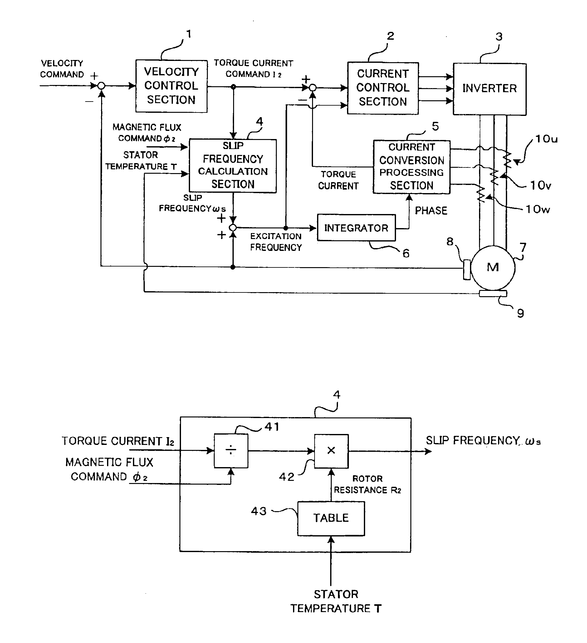
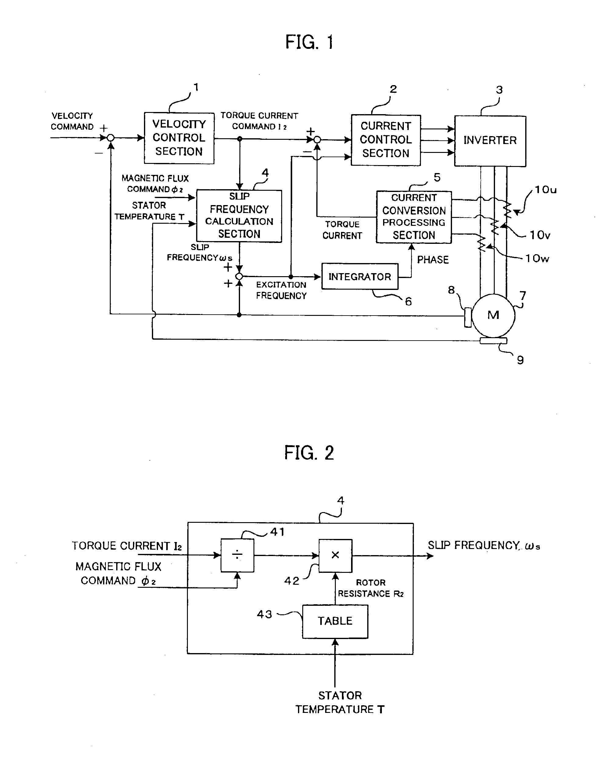
As shown in FIG. 1, a velocity of an induction motor 7 detected by a velocity detector 8 provided at the induction motor 7 is subtracted from a velocity command issued from a host numerical controller to obtain a velocity deviation. A velocity control section 1 obtains a torque command (rotor current command) I2 by performing PI (proportional plus integral) control. A slip frequency calculating section 4 receives the torque command I2, a magnetic flux (rotor magnetic flux) command Φ2 determined in accordance with a rotational velocity of the motor 7, and a temperature T detected by a temperature sensor 9 provided at a stator of the motor 7 and performs the processing as described later to obtain a slip frequency ωs. The velocity of the motor is added to the slip frequency ωs to obtain an excitation frequency and the obtained excitation frequency is outputted to a current control section 2.

The excitation frequency is integrated by an integrator 6 to obtain a phase. The current conver...


PUM


Abstract

A controller for a vector control of an induction motor, which is capable of easily determining a rotor resistance for use in calculation of a slip frequency. A temperature sensor is provided for detecting a temperature of a stator. Information on relation between the rotor temperature and the rotor resistance predetermined based on measurement is stored in a table. In driving the induction motor, the rotor resistance for the stator temperature detected by the temperature sensor is read from the table. A torque command I2 is divided by a magnetic flux command Φ2 and the obtained quotient is multiplied by the read value of the rotor resistance to obtain the slip frequency ωs, so that the vector control is performed based on the obtained slip frequency ωs. The value of the rotor resistance is easily determined by simply referring the table without complicated calculation. Since the stored information on the rotor resistance are based on measured values, a more precise value of the slip frequency is obtained to realize a precise vector control of the induction motor.

Description

BACKGROUND OF THE INVENTION1. Field of the InventionThe present invention relates to a controller for performing a vector control of an induction motor.2. Description of Related ArtThere is known a method of performing a vector control of an induction motor using a rotor resistance of the induction motor. However, it is necessary to perform temperature compensation on the rotor resistance since the rotor resistance varies with the temperature. It is difficult to directly detect an actual rotor resistance or the rotor temperature in operating the motor. Thus, in order to determine the rotor resistance, there has been proposed a method of estimating the rotor temperature based on a present value or historical values of a torque current of the motor and a predetermined thermal constant such as a thermal time constant, so that the rotor resistance is determined based on the estimated rotor temperature (e.g. JP 7-67400A).Further, there has been proposed a method of determining the rotor ...

Claims


Application Information

Patent Timeline
Patent Type & Authority Patents(United States)
IPC IPC(8): H02P21/00H02P21/08H02P21/13H02P21/22H02P23/07H02P27/04
CPCH02P21/10H02P21/085H02P21/09
Inventor IWASHITA, YASUSUKEAKIYAMA, TAKAHIROTEZUKA, JUNICHI
Owner FANUC LTD
Why Eureka
Try Eureka