
Light scattering detector

a detector and light scattering technology, applied in the direction of instruments, material analysis, withdrawing sample devices, etc., can solve the problems of difficult measurement of scattering function, inability to direct measure the scattering phase function, and no available sensor is known to accurately perform this measurement, etc., to achieve the effect of improving the signal strength

Inactive Publication Date: 2005-04-12
THE UNITED STATES OF AMERICA AS REPRESENTED BY THE SECRETARY OF THE NAVY
View PDF3 Cites 11 Cited by
  • Summary
  • Abstract
  • Description
  • Claims
  • Application Information

AI Technical Summary

Benefits of technology

Another object of the invention is to provide an apparatus for and method of measuring scattered light in water that can compensate for the progressively, rapidly decreasing magnitude of light scattered outside of the direction of the beam.
Another object of the invention is to provide an apparatus for and method of measuring the near-direct forward scattering function in water using one or more avalanche photo diodes to improve strength of signals.

Problems solved by technology

Historically, this scattering function has been difficult to measure, and no available sensors are known to accurately perform this measurement.
In fact, direct measurement of the scattering phase function has not been attempted often.
The arc the movable detector traveled was large, making it acceptable for effective real-time scientific measurements; however, the device was not suitable for general use at work sites in the ocean.
But these measurements are not directly relatable to the underlying scattering function, as they provide a measurement of integrated effects from which the scattering function cannot be extracted.

Method used


Image

  • Light scattering detector
  • Light scattering detector

Examples


Embodiment Construction

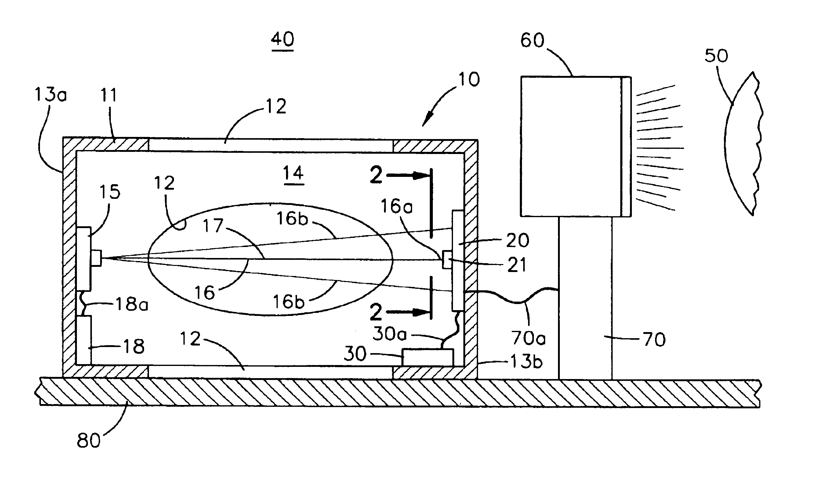
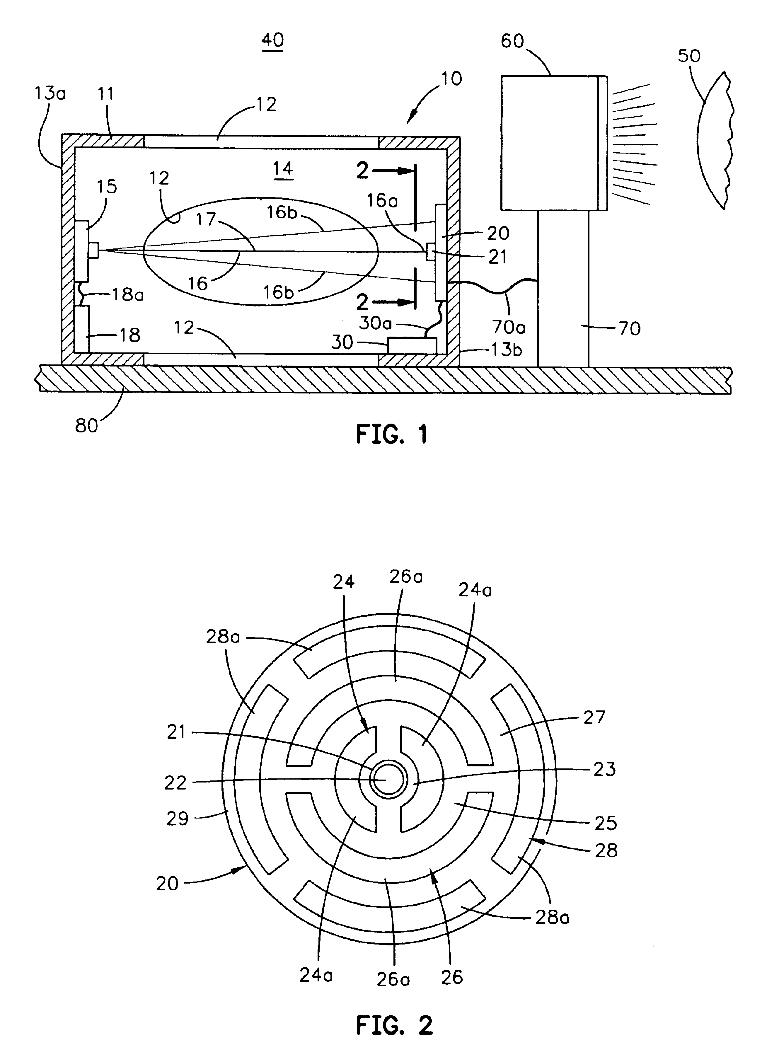
Referring to FIG. 1, detector 10 of this invention reliably measures the scattering, or scattering function of light. Detector 10 is particularly adapted to measure phenomena known as the near-direct forward scattering function in mediums, such as water 40. Knowing what this scattering function is enables more responsive detection, identification, and classification of objects, such as a mine 50 submerged in the harsh marine environment by a sensor module 60 connected to a processing system 70. The more responsive operation is assured since the performance of sensor module 60 is strongly influenced by the characteristics of the ambient water in which it is operating. Detector 10 of this invention can be compactly packaged and may be mounted adjacent sensor module 60 on a submersible platform 80 or other underwater mounting surface to provide real-time data representative of scattering functions for processing system 70 associated with sensor module 60. Optionally, detector 10 and pr...


PUM

PropertyMeasurementUnit
diameteraaaaaaaaaa
anglesaaaaaaaaaa
heightaaaaaaaaaa

Abstract

An apparatus and method permits measuring of near-direct forward scattering functions in water to enable acceptable underwater imaging for detection, classification, and identification of objects, such as mines. A source of light mounted on a housing member receiving ambient water emits a beam of light along an axis to a scattering detector assembly mounted on the base member. The detector assembly has a central active region disposed in the axis to receive portions of the light beam emitted along the axis and a plurality of concentric active regions are located radially outwardly from the central active region and the axis to receive scattered portions of the light beam. The central and concentric active regions provide signals representative of the magnitudes of the axial and scattered portions of the light beam for determination of the scattering function of the ambient water.

Description

BACKGROUND OF THE INVENTIONThis invention relates to an apparatus for measuring light scattering. More particularly, this invention measures near direct-forward scattering function of light in water for underwater imaging.Currently there is renewed interest in developing electro-optic sensors for underwater imaging used in the detection, classification, and identification of a number of submerged objects, such as mines. The performance of these sensors is strongly influenced by the characteristics of the water in which they are operated. For acceptable imaging one of the most influential environmental parameters which affects the performance is scattering. In particular, the parameter, or function of near-direct forward scattering that is attributed to the water medium and dissolved and particulate matter in the water medium dominates the ability to resolve fine details of images.Historically, this scattering function has been difficult to measure, and no available sensors are known...

Claims


Application Information

Patent Timeline
Patent Type & Authority Patents(United States)
IPC IPC(8): G01N21/47G01N21/49
CPCG01N21/49G01N2021/4707
Inventor LLOYD, JACK
Owner THE UNITED STATES OF AMERICA AS REPRESENTED BY THE SECRETARY OF THE NAVY
Learn More