Drive circuit for a MEMS device

Active Publication Date: 2005-04-12
LUMENTUM OPERATIONS LLC
View PDF14 Cites 20 Cited by
  • Summary
  • Abstract
  • Description
  • Claims
  • Application Information

AI Technical Summary

Benefits of technology

a power source for generating a relatively-low substantially-constant voltage;
an electric

Problems solved by technology

However, due to the elastic nature of the arms supporting the beam with the mirror, the device tends to oscillate or “ring” before coming to a complete stop.
Unfortunately, these devices still require a steady high voltage s

Method used


Image

  • Drive circuit for a MEMS device
  • Drive circuit for a MEMS device
  • Drive circuit for a MEMS device

Examples


Embodiment Construction

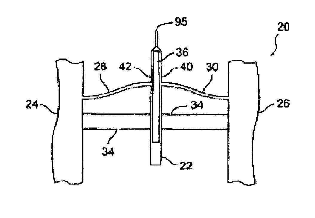
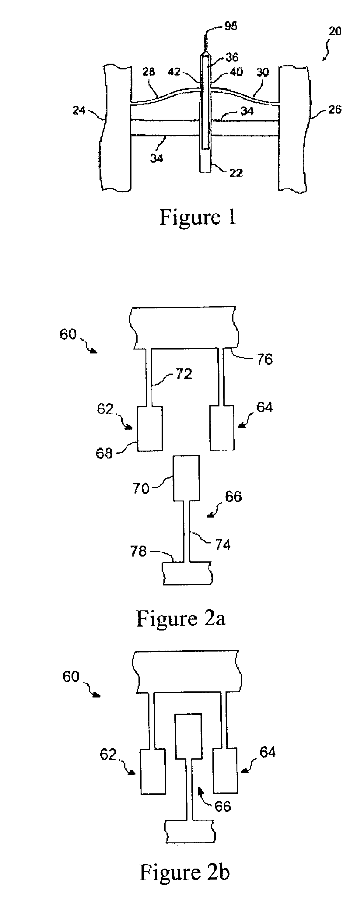
An example of a conventional MEMS device is illustrated in FIG. 1, in which a bi-stable 2×2 switch 20 includes a reciprocating center body 22 pivotally mounted to fixed supports 24 and 26 via spring arms 28 and 30, respectively. An actuator 34, as will be hereinafter described with reference to FIG. 2, is used to move the center body 22 between two stable positions. The center body 22 includes a hollow portion 36 defined by side walls 40 and 42. The hollow portion 36 enables the side walls 40 and 42 to slightly deform during actuation of the center body 22, thereby providing an energy barrier, i.e. a latch, that must be overcome before returning to the other position. Typically the end 95 of the center body 22 includes a reflective surface on each side thereof for reflecting optical signals between waveguides, as is well known in the art.

The actuator 34 can take several forms such as magnetic, electrical and electrostatic. FIG. 2a is a simplified top view of a portion of an electros...


PUM


Abstract

Small mechanical devices fabricated from semiconductor substrates called micro-electromechanical systems (MEMS) are used in the telecommunications industry for various purposes, such as switching and attenuation. Typically a small mirror or arm is moved into or out of the optical path of a beam of light to redirect of attenuate the signal. The present invention relates to a drive circuit for a MEMS device that converts a low voltage source into a higher more useful voltage pulse. The present invention also relates to an optically powered MEMS device utilizing the aforementioned drive circuit. Moreover, the drive circuit according to the present invention can be used to generate a single exponentially decaying pulse that can both generate an actuation force and a braking force for the MEMS device.

Description

TECHNICAL FIELDThe present invention relates to a drive circuit for a micro-electro-mechanical systems (MEMS) device, and in particular to a low voltage drive circuit that can be powered by light traveling in an optical network.BACKGROUND OF THE INVENTIONSwitches and other devices utilizing MEMS technology have recently become popular in the fiber optic communication industry due to their versatility, reproducibility, and durability. Conventional MEMS switches include a tiny reciprocating or pivoting mirror that requires a separate electrical power source to generate the voltage, e.g. 30V to 60V, required to move the mirror from a rest position to an active position. One such switch is disclosed in U.S. Pat. No. 6,303,885 issued Oct. 16, 2001 to Bryant Hichwa et al, which is incorporated herein by reference. The switch disclosed in the aforementioned reference is a bi-stable or latching MEMS switch that includes a mirror mounted on a reciprocating beam, which is supported by spring ...

Claims


Application Information

Patent Timeline
IPC IPC(8): G02B26/00G02F1/09G02F1/01G02B26/08
CPCG02B26/0841
Inventor WONG, JOHN DOUGLAS EVANADAMSON, ROBERTBURBIDGE, DOUGKLEPIKOV, VALERI
Owner LUMENTUM OPERATIONS LLC
Why Eureka
Try Eureka