
Boron-containing polymer compound and organic light emitting device using the same

a light-emitting device and boron-containing polymer technology, applied in the organic semiconductor device, discharge tube/lamp details, natural mineral layered products, etc., can solve the problems that light-emitting materials and organic light-emitting devices using the same cannot achieve a sufficiently high luminous efficiency at a low voltage, and achieve high driving voltage, high luminous efficiency, and increase the effect of emission area

Active Publication Date: 2007-07-19
SAMSUNG ELECTRONICS CO LTD
View PDF1 Cites 12 Cited by
  • Summary
  • Abstract
  • Description
  • Claims
  • Application Information

AI Technical Summary

Benefits of technology

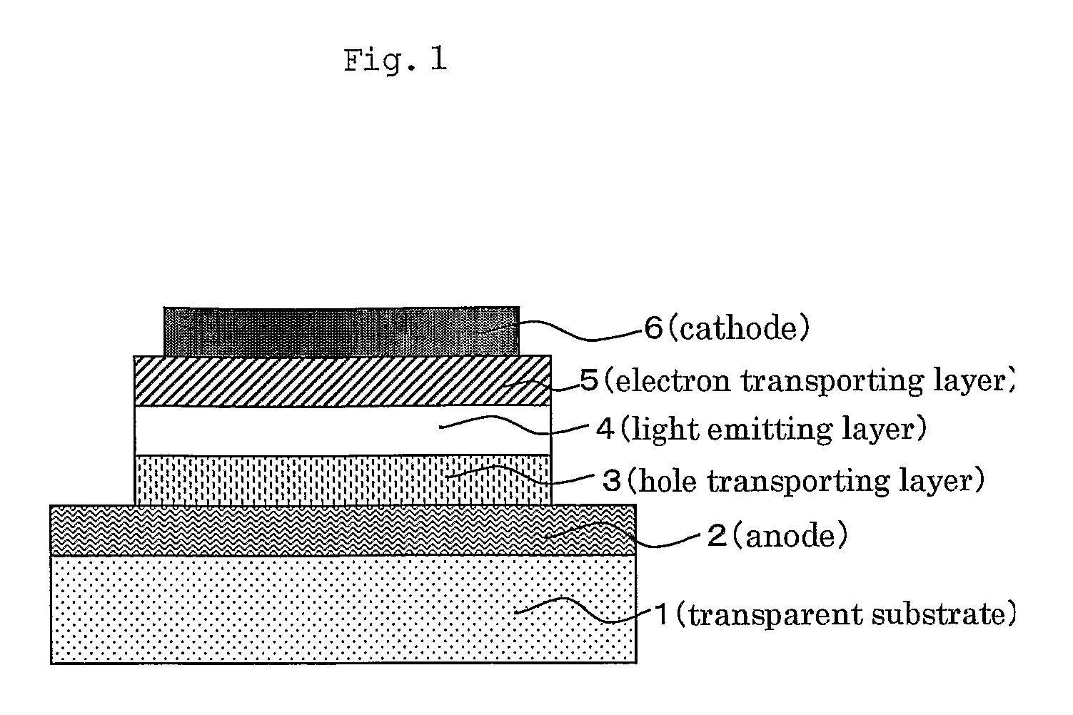
[0011] Accordingly, an object of the present invention is to provide a polymer material which can show a high luminous efficiency at a low voltage and is suitable for increasing the emission area and for the mass production, and an organic light emitting device using the same.
[0071] Further, for the purpose of improving the physical properties, etc. of the film formed of the polymer compound, a polymer compound having no direct effect on the light emitting properties of the polymer compound may be added and thus-obtained composition may be used as a light emitting material. For example, polymethyl methacrylate (PMMA) may be added to make the resultant film flexible.

Problems solved by technology

Though high-efficient light-emitting polymer materials suitable for increasing emission area and for mass production have been developed, a light-emitting material and an organic light emitting device using the same capable of showing a sufficiently high luminous efficiency at a low voltage have not yet been obtained.

Method used


Image

  • Boron-containing polymer compound and organic light emitting device using the same
  • Boron-containing polymer compound and organic light emitting device using the same
  • Boron-containing polymer compound and organic light emitting device using the same

Examples


example 1

Synthesis of Polymerizable Compound (Boron Monomer Compound 1)

[0095]

(1) Preparation of Grignard Reagent

[0096]

[0097] Under a nitrogen atmosphere, to a 100 ml-volume four-neck flask, 1.00 g of magnesium, 5 ml of dry tetrahydrofuran (THF) and 2 mg of iodine were charged and stirred at room temperature until there is no iodic color. Thereto was added a solution prepared by dissolving 7.30 g of 4-bromostyrene in 30 ml of dry tetrahydrofuran (THF) dropwise to be a reaction temperature of 15 to 20° C. in a dry-ice / methanol bath. After dropping, the reaction solution was stirred for 60 minutes while keeping the temperature of 15 to 20° C. to prepare a Grignard reagent (StyMgBr).

(2) Synthesis of Triarylboron

[0098]

[0099] under a nitrogen atmosphere, to a 200 ml-volume four-neck flask, 4.16 g of dimesitylboronfluoride and 10 ml of toluene (Tol) were charged. Thereto was added the Grignard reagent (StyMgBr) prepared above to be a temperature of 15 to 20° C., and then stirred for 6 hours whi...

example 2

Synthesis of Polymerizable Compound (Boron Monomer Compound 2)

[0102]

(1) Synthesis of 1-bromo-2,6-dimethyl-4-tert-buthyldimethylsiloxybenzene (Compound 3)

[0103]

[0104] Under a nitrogen atmosphere, to a 100 ml-volume three-neck flask, 5.00 g of 4-bromo-3,5-dimethylphenol, 3.87 g of tert-buthyl dimethylchlorosilane, 10 ml of dry dichloromethane (DCM) and 3 ml of dry dimethylformamide (DMF) were charged and stirred. While stirring, thereto was added a solution prepared by dissolving 1.75 g of imidazole in 10 ml of dry DCM dropwise. After dropping, the reaction solution was stirred for 3 hours at room temperature. Then, the generated impurities were separated by filtration and the filtrate was concentrated under a reduced pressure, and ethyl acetate and 5% aqueous sodium hydrogencarbonate solution were added thereto. The organic layer was separated and washed with water and saturated saline and dried over anhydrous sodium sulfate. After the drying agent was filtered out and the solvent ...

example 3

Synthesis of Polymerizable Compound (Boron Monomer Compound 7)

[0117]

(1) Synthesis of dimesityl(4-styryl-2,6-dimethylphenyl)borane (Compound 7)

[0118]

[0119] To a 100 ml-volume eggplant type flask, 2.22 g of Compound 6 and 12 ml of dry dioxane, 1.66 g of tributyl vinyl tin, 0.64 g of anhydrous lithium chloride, 0.11 g of tetrakis(triphenylphosphine)palladium and 0.03 g of 2,6-di-tert-butyl-4-methyl-phenol were charged and stirred for 3 hours at hot water temperature of 100° C. After standing to cool, thereto was added 2.7 ml of pyridine and 3.2 ml of 1.4M pyridinium fluoride tetrahydrofuran (THF) solution and stirred overnight at room temperature. After that, 10 ml of ethyl acetate was added to the reaction solution and the insoluble matters were separated by filtration. The filtrate was washed with water, 4N hydrochloric acid, water, 4N sodium hydroxide, water and saturated saline in this order and dried over anhydrous sodium sulfate. After the drying agent was filtered out and the ...


PUM

PropertyMeasurementUnit
atomic numbersaaaaaaaaaa
external quantum efficiencyaaaaaaaaaa

Abstract

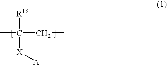
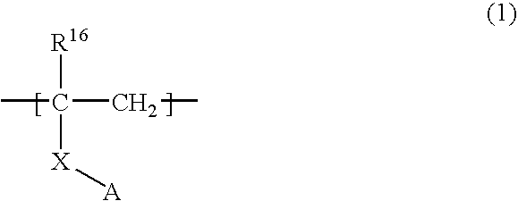
The present invention provides a polymer material showing high luminous efficiency at a low voltage and suitable for increasing the emission area and for the mass production, and an organic light emitting device using the same. The present invention relates to a polymer compound comprising a boron-containing monomer unit represented by formula (1): [in the formula, A represents a triphenyl boron group in which the phenyl group may be substituted, R16 represents a hydrogen atom or an alkyl group having 1 to 12 carbon atoms. X represents a single bond, —O—, —S—, —SO—, —SO2— or a divalent hydrocarbon group having 1 to 20 carbon atoms which may have a hetero atom], a light-emitting polymer compound comprising the boron-containing monomer unit and a light-emitting monomer unit, a light-emitting composition comprising the boron-containing monomer unit and a light-emitting low-molecular compound or light-emitting polymer compound, and organic light-emitting device using the light-emit-ting polymer compound or the light-emitting composition.

Description

CROSS-REFERENCE TO RELATED APPLICATIONS [0001] This is an application filed pursuant to 35 U.S.C. Section 111(a) with claiming the benefit of U.S. provisional application Ser. No. 60 / 532,919 filed Dec. 30, 2003 under the provision of 35 U.S.C. 111(b), pursuant to 35 U.S.C. Section 119(e) (1).TECHNICAL FIELD [0002] The present invention relates to an organic light emitting device (OLED) used for backlights in flat display panels or the like. More specifically, the present invention relates to a boron-containing polymer compound used for a light-emitting layer in an organic light emitting device and an organic light emitting device using the polymer compound. BACKGROUND ART [0003] Materials and structures of organic light emitting devices have been improved rapidly since C. W. Tang, et al. of Eastman Kodak Company demonstrated a high-luminance in 1987, and the devices have recently been put into practical use in displays of car audio systems and cellular phones, etc. To further widen ...

Claims


Application Information

Patent Timeline
Patent Type & Authority Applications(United States)
IPC IPC(8): C08F30/06H01L51/54C09K11/06C08F8/00C08F8/42C08F230/06H10K99/00
CPCC08F8/42Y10S428/917C08F230/06C09K11/06C09K2211/1029C09K2211/1033C09K2211/1037C09K2211/1088C09K2211/1092C09K2211/1416C09K2211/1425C09K2211/1433C09K2211/185H01L51/0037H01L51/004H01L51/0043H01L51/0059H01L51/0062H01L51/0079H01L51/008H01L51/0085H01L51/5012H01L51/5016H01L2251/308H05B33/14C08F30/06C08F230/065H10K85/1135H10K85/141H10K85/151H10K85/649H10K85/631H10K85/321H10K85/342H10K50/11H10K2101/10H10K2102/103H10K50/00H10K85/658H10K10/00H10K85/322
Inventor KATO, TSUYOSHIKONDO, KUNIO
Owner SAMSUNG ELECTRONICS CO LTD
Learn More