

Wavelength conversion apparatus
a wavelength conversion and wavelength technology, applied in the field of wavelength conversion apparatus, can solve the problem of limited injection power of pumping light, the upper limit value of injection power, etc., and achieve the effect of increasing the conversion efficiency of fwm operation, increasing the pumping light power, and improving the efficiency of fwm
- Summary
- Abstract
- Description
- Claims
- Application Information
AI Technical Summary
Problems solved by technology
Method used
Image

Examples
first embodiment
(2) First Embodiment
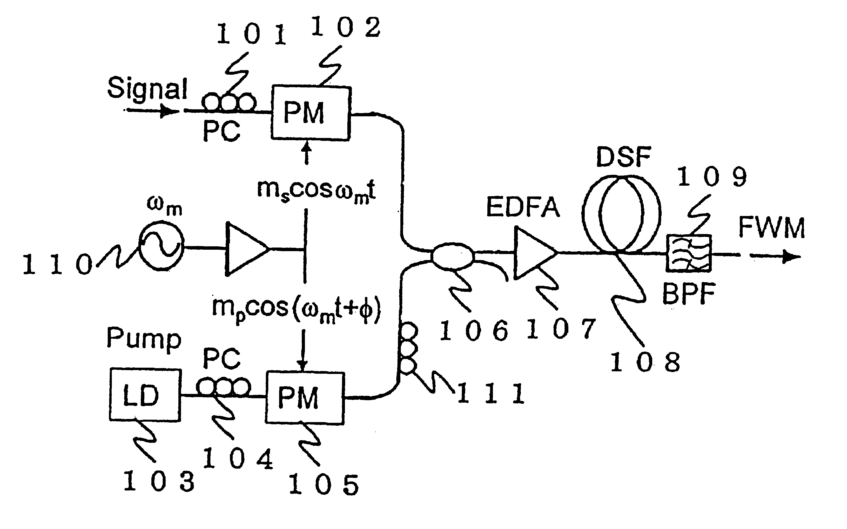
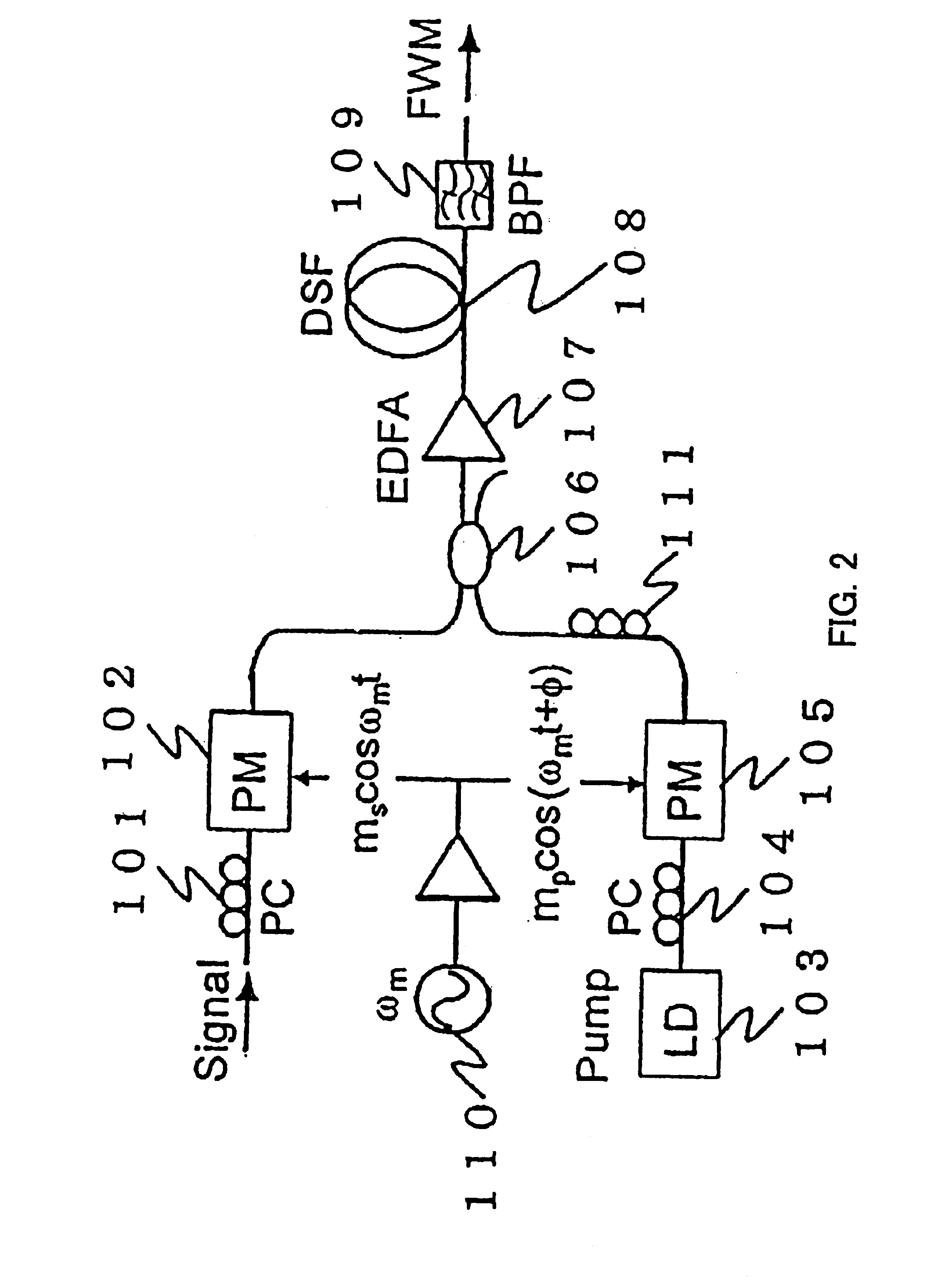
FIG. 2 is a structural diagram for showing a wavelength conversion apparatus according to a first embodiment mode of the present invention. This drawing shows an arrangement in which both signal light and pumping light are phase-modulated. The wavelength conversion apparatus of this embodiment mode is provided with polarization controllers (PCs) 101, 104, 111; phase modulators (PMs) 102, 105; a laser diode (LD) 103; a coupler 106; an Eribuim-doped fiber amplifier (EDFA) 107; a dispersion-shifted fiber (DSF) 108; a band-pass filter (BPF) 109; and an oscillator 110.
The laser diode (LD) 103 is a light emitting unit for outputting pumping light (Pump). The polarization controllers (PCs) 101, 104, and 111 control polarization planes of input light. The oscillator 110 outputs a modulation signal. The phase modulators (PMs) 102 and 105 phase-modulate signal light (Signal) and pumping light (Pump) based upon the modulation signal outputted from the oscillator 110, respec...
second embodiment
(3) Second Embodiment
FIG. 3 is a structural diagram for showing a wavelength conversion apparatus according to a second embodiment mode of the present invention. This drawing shows an arrangement in which both FWM light and pumping light are phase-modulated. The wavelength conversion apparatus of this embodiment mode is provided with polarization controllers (PCs) 101, 104, 111; phase modulators (PMs) 105, 301; a laser diode (LD) 103; a coupler 106; an Eribuim-doped fiber amplifier (EDFA) 107; a dispersion-shifted fiber (DSF) 108; a band-pass filter (BPF) 109; and an oscillator 110. The phase modulator (PM) 301 phase-modulates input light based upon a modulation signal outputted from the oscillator 110, and then outputs the phase-modulated input light. Other structural elements of this embodiment mode are similar to those of FIG. 2.
Pumping light derived from the laser diode (LD) 103 penetrates the polarization controller (PC) 104, and then, is phase-modulated based upon the modulati...
third embodiment
(4) Third Embodiment
Next, FIG. 4 is a structural diagram for showing a wavelength conversion apparatus according to a third embodiment mode of the present invention. This drawing shows an arrangement in which signal light is phase-modulated, and pumping light is directly frequency-modulated. The wavelength conversion apparatus of this embodiment mode is provided with polarization controllers (PCs) 101, 104; a phase modulator (PM) 102; a laser diode (LD) 401; a coupler 106; an Eribuim-doped fiber amplifier (EDFA) 107; a dispersion-shifted fiber (DSF) 108; a band-pass filter (BPF) 109; and an oscillator 110. The laser diode (LD) 401 corresponds to such a light emitting unit for frequency-modulating pumping light based upon a modulation signal outputted from the oscillator 110, and then, for outputting the frequency-modulated pumping light. Other structural elements of this wavelength conversion apparatus are similar to those of FIG. 2.
The signal light is entered via the polarization c...
PUM
| Property | Measurement | Unit |
|---|---|---|
| wavelength | aaaaa | aaaaa |
| flexibility | aaaaa | aaaaa |
| wavelength conversion | aaaaa | aaaaa |
Abstract
Description
Claims
Application Information