
Method and device to evaluate signals of a sensor to monitor a textile machine

a technology of textile machines and sensors, applied in the direction of instruments, force/torque/work measurement, apparatus for force/torque/work measurement, etc., can solve the problems of unsuitability, high delivery speed of over 1,000 meters per minute, and inconvenient us

Inactive Publication Date: 2005-04-19
RIETER INGOLSTADT SPINNEREIMASCHENBAU AG
View PDF9 Cites 5 Cited by
  • Summary
  • Abstract
  • Description
  • Claims
  • Application Information

AI Technical Summary

Benefits of technology

"The present invention provides a precise and economical evaluation method and device for evaluating the state of fiber sliver using microwave technology. The method involves using a microwave sensor or its assigned high-frequency device to provide a number of first digital signals in a digital form per time unit. These signals are then used to calculate second digital signals, which indicate the current sliver thickness or sliver mass of the fiber sliver. These second signals are then used to level the drafting equipment and adjust the controllable drafting equipment. The invention allows for the efficient use of microwave technology in evaluating fiber sliver state, reducing the number of first signals needed to be processed and allowing for precise control of the drafting equipment. The second signals can also be used to form a mean value or a predetermined length of fiber sliver, providing sufficient description of the state of the fiber sliver. Overall, the invention provides a more efficient and precise method for evaluating fiber sliver state."

Problems solved by technology

This mechanical scanning is at a disadvantage at extremely high delivery speeds of over 1,000 meters per minute, as is common in modern high-performance draw frames.
Furthermore, the intensive mechanical compression required with mechanical sensors has a negative effect on the subsequent drafting process.
These methods have however individual disadvantages that made them seem unsuited until now for continuous industrial application in the textile industry.
In such a case, the fact that as the time-dependent signals are assigned to the proper location in the fiber sliver, a great computing expenditure is disadvantageously required because of the great quantity of data supplied.
This is difficult to achieve by means of a microwave sensor and at reasonable cost, especially with very rapidly running fiber slivers.
This expensive procedure is costly and subject to errors, because of the occurrence of the undesirable phase shift and quantization errors.

Method used


Image

  • Method and device to evaluate signals of a sensor to monitor a textile machine
  • Method and device to evaluate signals of a sensor to monitor a textile machine
  • Method and device to evaluate signals of a sensor to monitor a textile machine

Examples


Embodiment Construction

[0039]Reference will now be made in detail to the presently preferred embodiments of the invention, one or more examples of which are shown in the figures. Each example is provided to explain the invention, and not as a limitation of the invention. In fact, features illustrated or described as part of one embodiment can be used with another embodiment to yield still a further embodiment. It is intended that the present invention cover such modifications and variations.

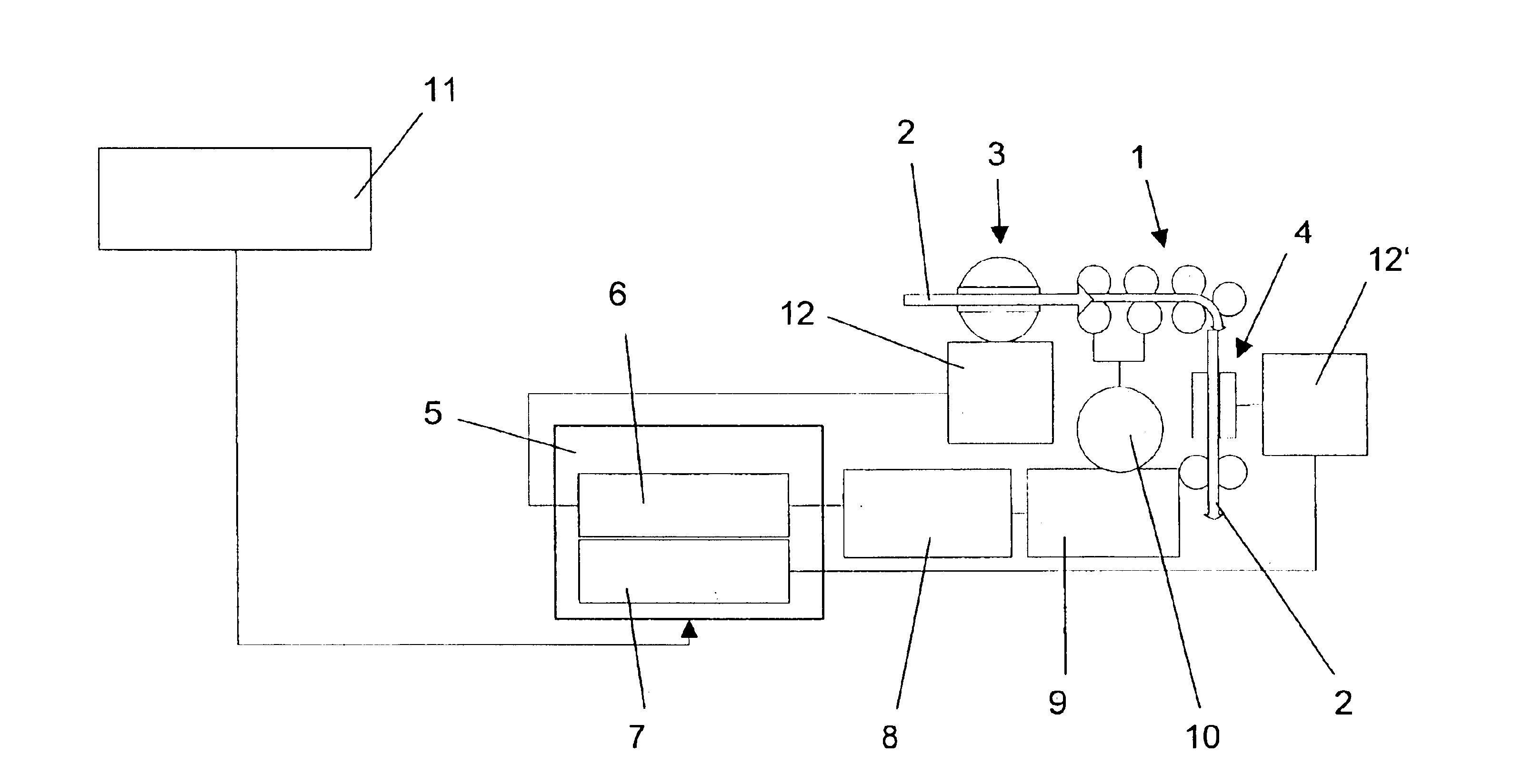
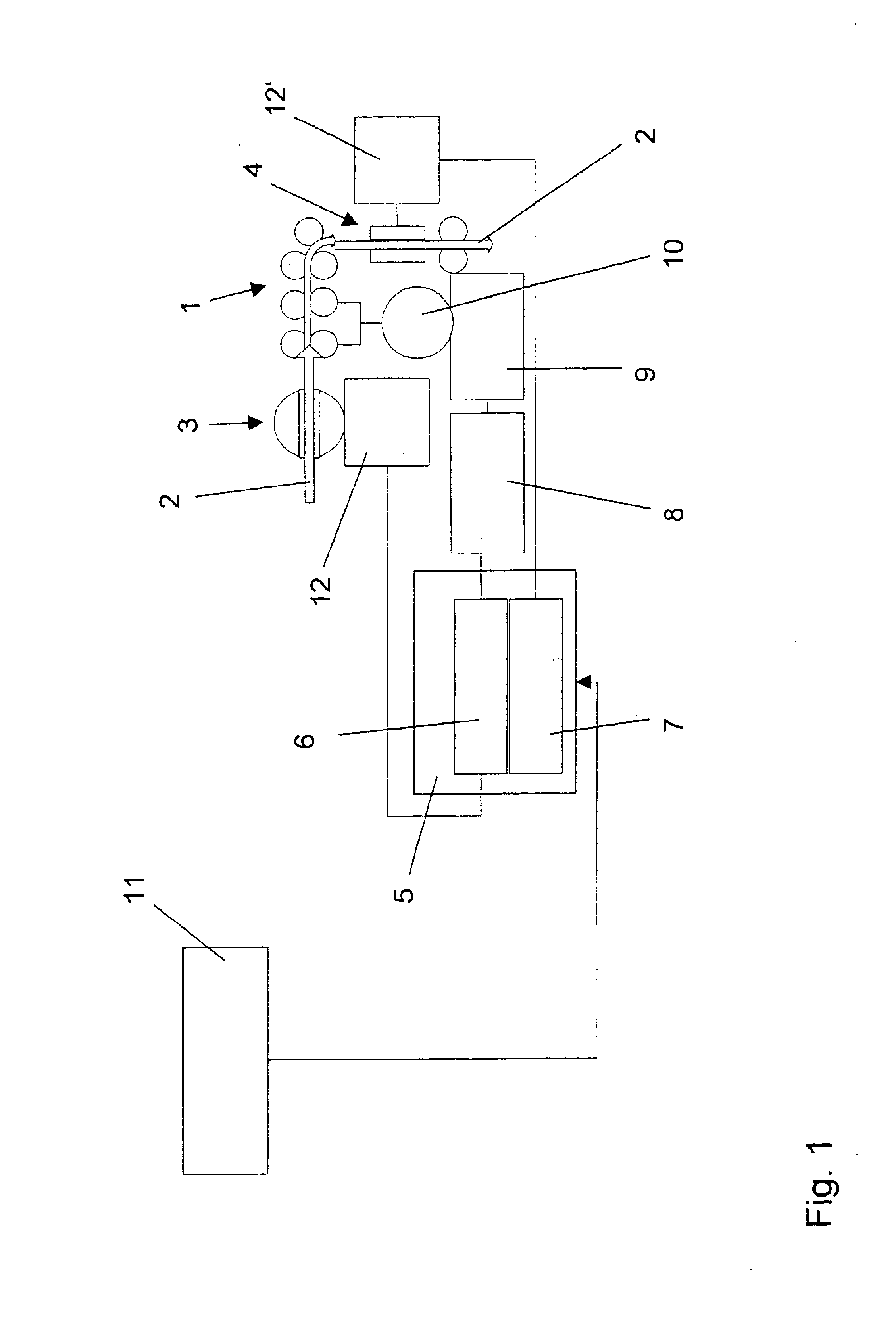
[0040]FIG. 1 shows a simplified block diagram of drafting equipment 1 with microwave sensors. A fiber sliver 2 runs into the drafting equipment 1 in the direction of the arrow and comes out in the form of drafted fiber sliver 2′. Normally several fiber slivers 2 are at the input of the drafting equipment 1 and are united into one fiber sliver 2′ by the drafting equipment at its outlet.

[0041]At the inlet of the drafting equipment 1, an inlet sensor 3 is installed. The inlet sensor 3 functions with microwave technology a...


PUM

PropertyMeasurementUnit
lengthaaaaaaaaaa
lengthaaaaaaaaaa
distanceaaaaaaaaaa

Abstract

A method and device for the evaluation of signals of a sensor, in particular of a microwave sensor, is proposed for the detection of the thickness, mass, density and / or moisture of at least one fiber sliver moving relative to the sensor on drafting equipment. A high-frequency unit assigned to the sensor produces a number of first digital signals in digital form of the current state of the (at least one) fiber sliver. The method according to the invention is characterized in that a second digital signal, representing the current sliver thickness or sliver mass of the (at least one) fiber sliver and which is then used to control the drafting equipment and / or to judge the fiber sliver quality, is formed according to an algorithm from the first digital signals made available. In addition a suitable device for the evaluation of the signals of a sensor is proposed.

Description

FIELD OF THE INVENTION[0001]The invention relates to a process to evaluate signals of a sensor, in particular of a microwave sensor to detect thickness, mass, density and / or moisture of at least one fiber sliver moving in relation to the sensor on drafting equipment, whereby a high-frequency device assigned to the sensor produces a number of first signals in digital form concerning the current state of the (at least one) fiber sliver, as well as to a device for the evaluation of the signals of such a sensor. In addition, the invention relates to a textile machine with such a device.BACKGROUND OF THE INVENTION[0002]In the textile industry, fiber slivers with a cross section consisting of a plurality of individual fibers are often measured for thickness, mass, density and / or moisture. This is necessary, e.g., in the area of drafting equipment in order to draft one or several fiber slivers to reduce the number or mass of their fibers in the cross-section of fiber slivers. It is then of...

Claims


Application Information

Patent Timeline
Patent Type & Authority Patents(United States)
IPC IPC(8): D01H5/38D01G31/00D01H5/00
CPCD01H5/38D01G31/006
Inventor CHERIF, CHOKRIUEDING, MICHAEL
Owner RIETER INGOLSTADT SPINNEREIMASCHENBAU AG
Learn More