
Method for manufacturing a three-phase transformer

Inactive Publication Date: 2005-04-19
A T T ADVANCED TRANSFORMER TECH
View PDF31 Cites 16 Cited by
  • Summary
  • Abstract
  • Description
  • Claims
  • Application Information

AI Technical Summary

Benefits of technology

[0015]It is a major feature of the present invention to provide such a transformer that has higher efficiency and smaller magnetic core, and that uses lower quantities of materials per unit electrical power and / or has better maintainability, as compared to those of the conventional transformers of this kind.

Problems solved by technology

This method is costly and labor-intensive.
The transformers having amorphous metal cores manufactured according to this method cannot be repaired without causing damage to the core.
The operation, however, is time-consuming and labor-intensive.
Although the coated cores have good magnet properties, their manufacture requires costly and complex operational steps.
Moreover, the method of repairing these cores is labor-intensive.
Another common disadvantage of the transformers manufactured according to the techniques disclosed in the above patents is that annealed amorphous metals become extremely brittle, and thus break under mechanical stress, for example, during the stage of closing the core joint.
However, to manufacture a transformer in accordance with the technique disclosed in U.S. '705, complex production technology as well as a complex repair technology, are required.
However, the commercially available amorphous ribbons (strips) are typically limited in width (up to 200 mm).
This technique, however, suffers from energy losses caused by unavoidable introduction of unwanted air gaps between each two adjacent toroids.

Method used


Image

  • Method for manufacturing a three-phase transformer
  • Method for manufacturing a three-phase transformer
  • Method for manufacturing a three-phase transformer

Examples


Embodiment Construction

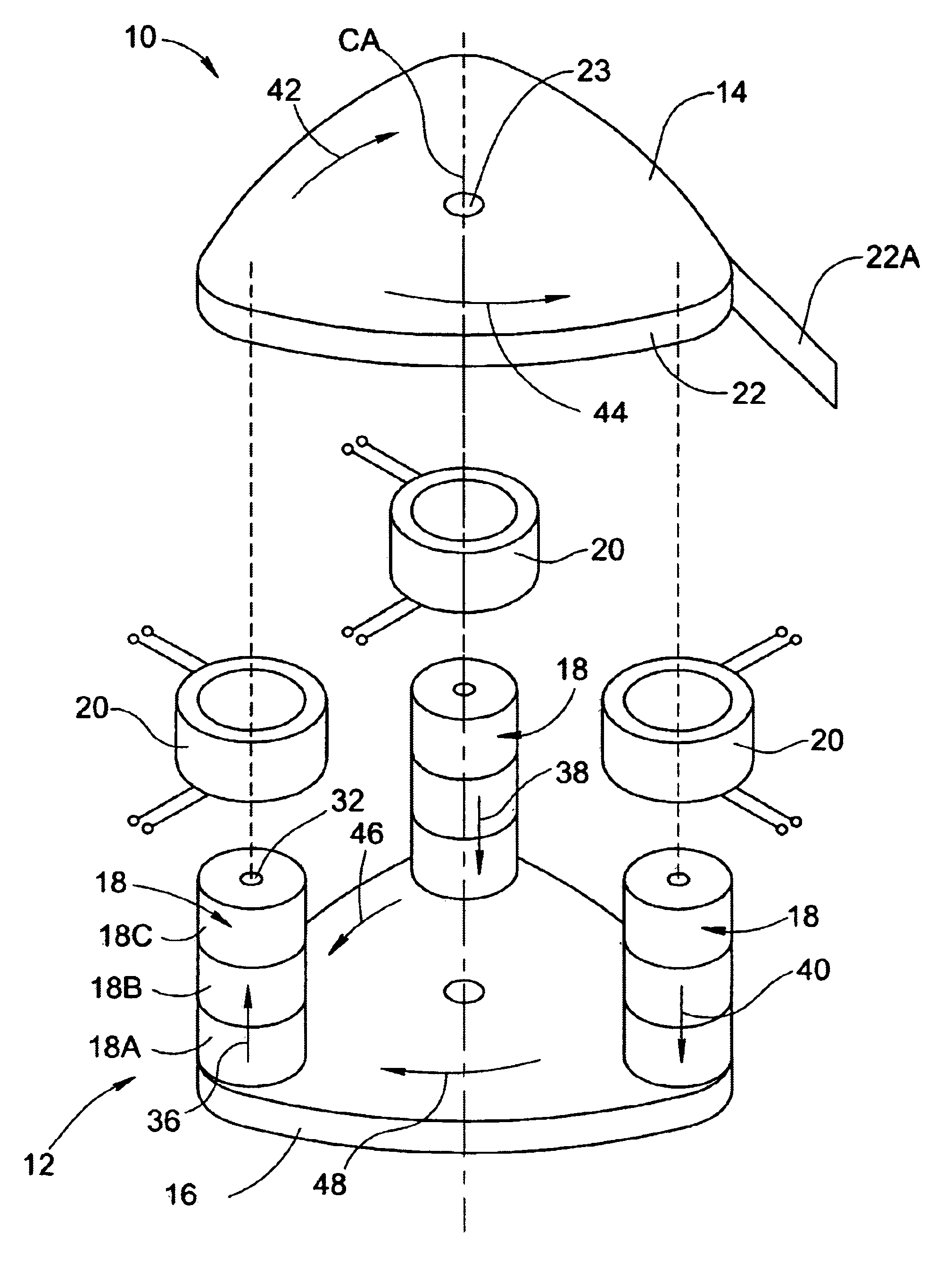
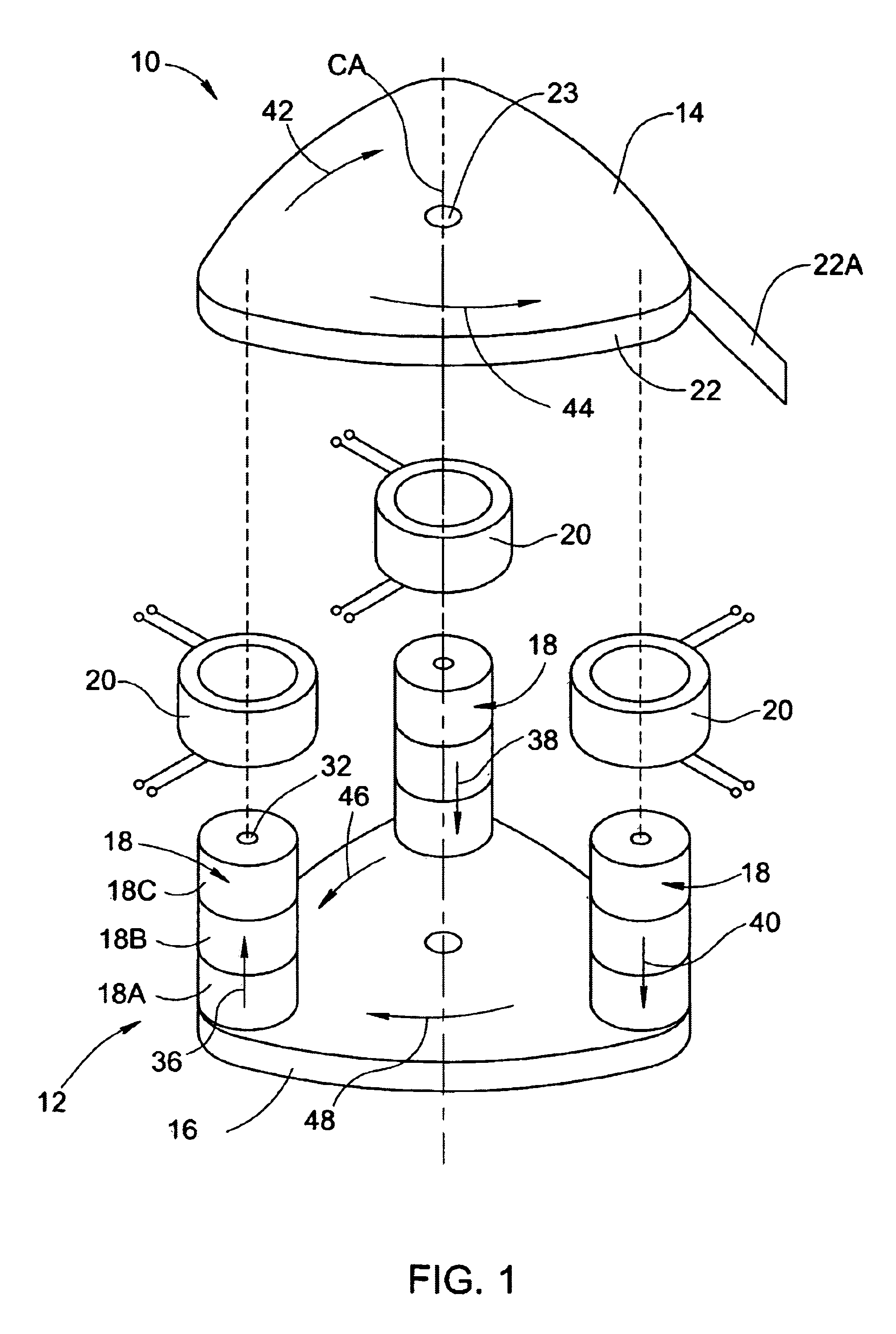
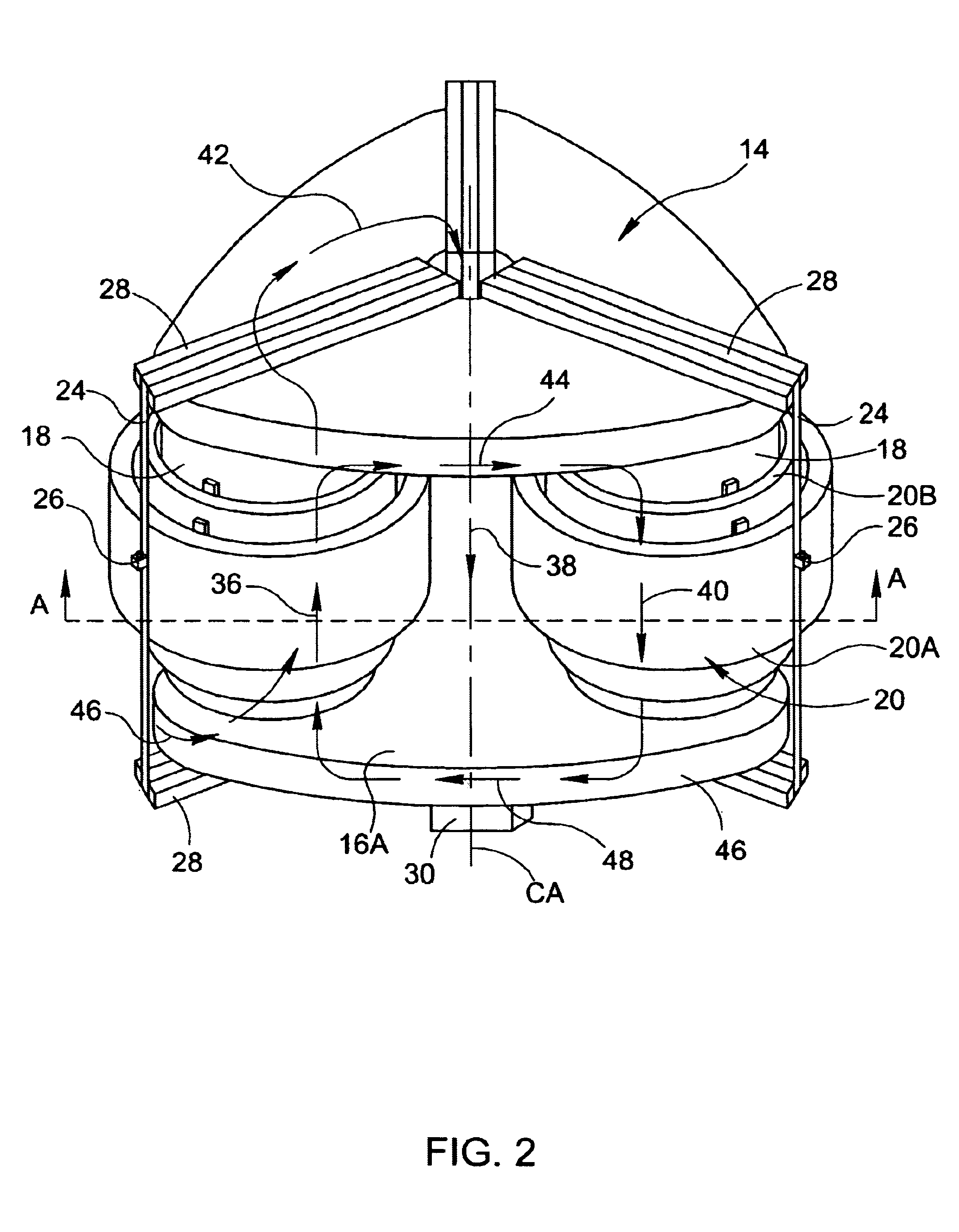
[0044]Referring to FIGS. 1 and 2, the main components of a three-phase transformer 10 constructed according to the present invention are illustrated. The transformer 10 comprises a magnetic circuit 12 formed by an upper plate-like element 14, a lower plate-like element 16, and tee parallel identical column-like elementary circuits, generally at 18. The magnetic circuit 12 is arranged such that the plates 14 and 16 are parallel to each other, and the columns 18 serve as supports between the plates, thereby forming a cage-like structure spatially symmetrical about a central axis CA. In the present example, each of the plates 14 and 16 is a toroid, and is made of amorphous ribbons 22 wound about a central hole 23 to form the planar toroid. Further provided are three coil blocks 20, each for mounting on a corresponding, one of the columns 18. As shown in FIG. 2, each of the coil blocks 20 includes a primary winding 20a and a secondary winding 20b. Thus, each phase of the transformer 10 ...


PUM

PropertyMeasurementUnit
Lengthaaaaaaaaaa
Magnetic fieldaaaaaaaaaa
Widthaaaaaaaaaa

Abstract

A three-phase transformer and a method of its manufacture are presented. The transformer comprises a magnetic circuit and three coil blocks. The magnetic circuit comprises two spaced-apart, parallel, plate-like elements; and three spaced-apart, parallel column-like elementary circuits. Each of the column-like elementary circuits carries the corresponding one of the three coil blocks, and serves for the corresponding one of the three phases. The column-like elementary circuits are substantially perpendicular to the plate-like elements, and are enclosed therebetween such as to form a spatial symmetrical structure about a central axis of the transformer. Each of the column-like elementary circuits is substantially a toroid in the form of a multi-layer structure formed by winding a predetermined number N of packages of magnetic strips about a central axis of the toroid, each package being composed of a predetermined number n of layers formed by n strips placed on top of each other.

Description

RELATED APPLICATION[0001]This application is a Continuation In Part of Ser. Nos. PCT / IL99 / 00562 filed Oct. 25, 1999 and PCT / IL00 / 00243 filed Apr. 27, 2000.FIELD OF THE INVENTION[0002]This invention relates to a three-phase electrical transformer and a method for manufacturing thereof.BACKGROUND OF THE INVENTION[0003]A transformer is a known electrical device widely used for transferring energy of an alternating current in the primary winding to that in one or more secondary windings. It typically contains two or more electrical circuits comprising primary and secondary windings, each made of a multi-turn coil of electrical conductors with one or more magnetic cores coupling the coils by transferring a magnetic flux therebetween.[0004]Presently known three-phase transformers usually utilize E+1 magnetic cores in a flat structure. Such a transformer includes several interconnected magnetic cores located in one plane. U.S. Pat. Nos. 4,893,400 and 5,398,402 disclose transformers having ...

Claims


Application Information

Patent Timeline
IPC IPC(8): H01F27/25H01F30/12H01F30/06H01F3/04H01F41/02
CPCH01F27/25H01F30/12Y10T29/49073Y10T29/49009Y10T29/49071Y10T29/49078Y10T29/4902
Inventor BOLOTINSKY, YURIRUBSHTEIN, ALEXANDERSAVULKIN, MICHAELADAR, ELIEZER
Owner A T T ADVANCED TRANSFORMER TECH
Learn More