Al technical title is built by PatSnap Al team. It summarizes the technical point description of the patent document.
a technology of diversion system and diversion system, which is applied in the direction of roof drainage, machine supports, manufacturing tools, etc., can solve the problems of system malfunction, and significant problems, and achieve the effect of precipitating roof and structural rotting as well as erosion
Inactive Publication Date: 2005-04-19
SENOX
View PDF8 Cites 18 Cited by
Summary
Abstract
Description
Claims
Application Information
AI Technical Summary
This helps you quickly interpret patents by identifying the three key elements:
Problems solved by technology
Method used
Benefits of technology
[0015]Methods are provided for installation of a rain diversion system including formation of a deflector with a machine placed above a forming machine dedicated to formation of a trough. As trough is run from a first machine, end caps are installed, outlet sites are punched and outlets installed for joinder with downspouts, miters are cut, where appropriate, and a cavity structure of the hanger is brought into place to mate a containment lip of the hanger with the containment shelf of the trough. Corresponding deflector is run from a second machine and the deflector is placed on the trough as deflector attachment cavities o...
Problems solved by technology
Diversion or gutter systems devised with open-channeled rain gutters tend to accumulate debris including sticks, leaves and other matter that is swept toward the gutter by the gravity-induced flow of water down the pitch of the roof.
Such debris can cause malfunction of the system as well as significant problems with leakage and corrosion.
Roof and structural rotting as well as erosion can be precipitated by the consequent accumulation of water without appropriate attendant diversion.
These techniques commonly have their own debris accumulation problems.
As diversions systems have become more complicated, so have the associated issues of cost, specialized material stock, and installation efficiency become more unwieldy.
For example, most systems that employ a deflector affix the deflector with screws or clips that reduce flexibility of the system or add an extra part (in addition to the hanger) to the assembly.
If the deflector cannot be easily unfastened from the gutter, repair and maintenance are complicated.
For a variety of reasons, diversion systems that deflect debris have not been adopted as widely as demand would suggest.
Non-standard coil sizes add significantly to the cost and availability of such systems.
With known designs, if standard width coil of 11⅞ inches were used to form the trough, the shift of material around the standard trough form factor (as employed in the art to create the “OG” 5 inch gutter) from the front trough channel containment wall to the back wall of the trough to provide sufficient deflector inclination leaves insufficient material for the front This process takes, however, material from the front...
Method used
Image
Click on the blue label to locate the original text in one second.
Reading with bidirectional positioning of images and text.
Examples
Embodiment Construction
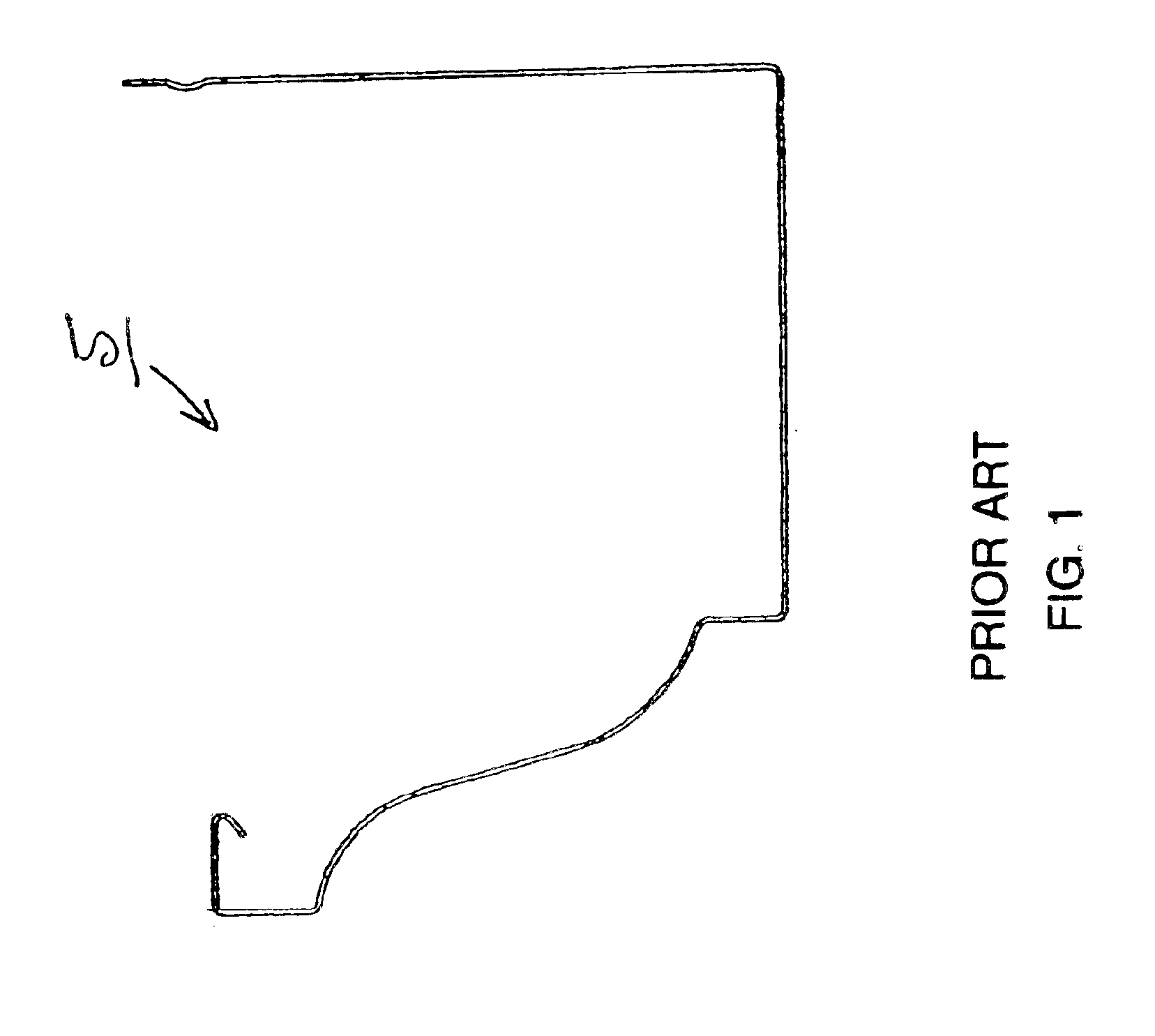
[0031]FIG. 1 depicts a cross-sectional view of a prior art trough 5 of standard configuration that is common in the field. As shown in FIG. 1, the depicted trough 5 has a folded edge or shelf along its front containment wall.
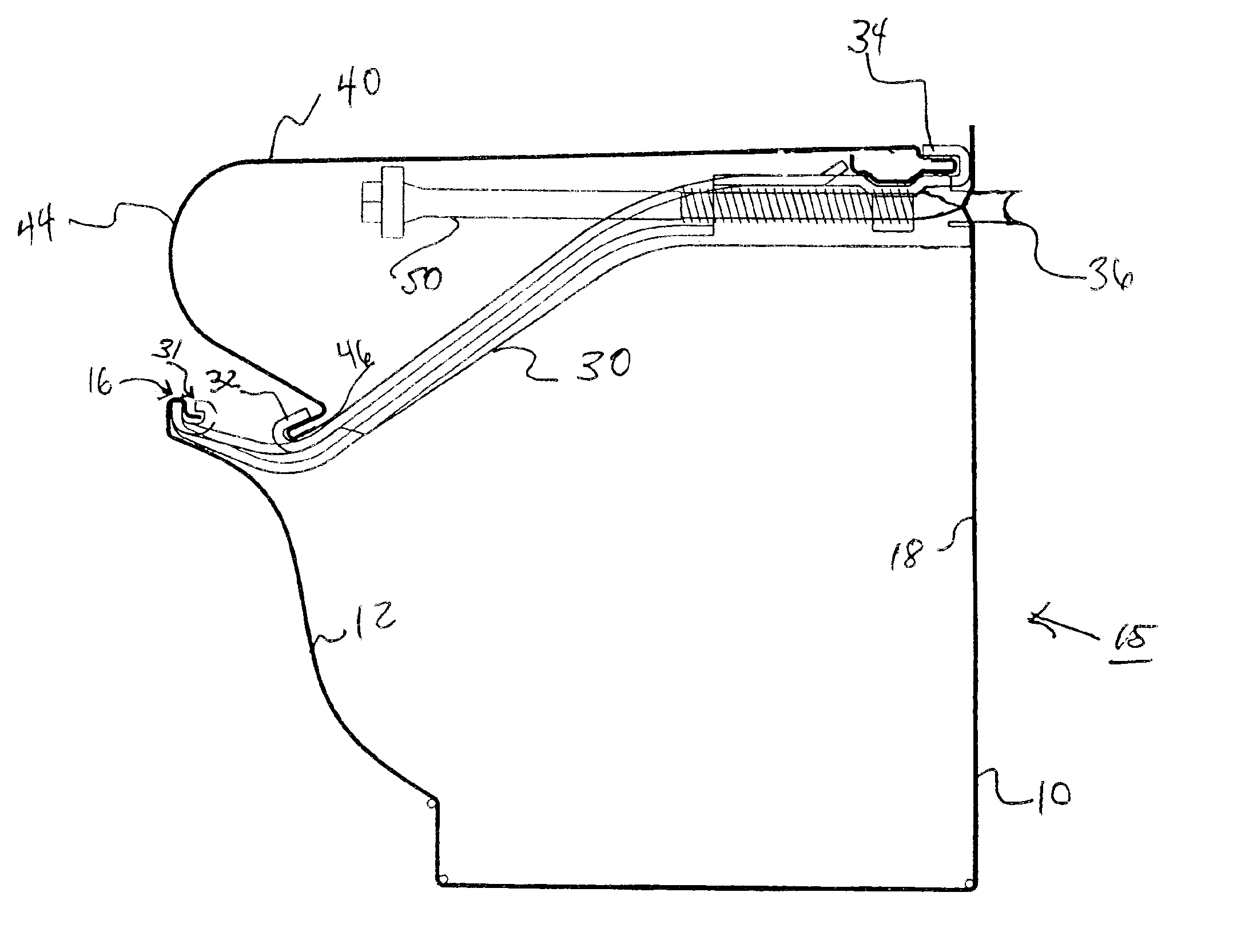
[0032]FIG. 2 depicts a cross-sectional view of a trough 10 configured in accordance with a preferred embodiment of the present invention. Trough 10 has a front containment wall 12 that has an inwardly projecting shelf 14 that is part of containment wall border area 16 of front containment wall 12. Trough 10 has a back wall 18. As shown, containment wall 12 need not be a planar wall but may take a variety of shapes and configurations to provide a containment function for collected liquid. Between front containment wall 12 and back wall 18, a channel is formed for water collection and diversion bottomed with floor 20. In an embodiment having a rounded or “half-round” trough, it will be recognized that there is no distinct floor 20 and front containment wall 12 and...
PUM
Property
Measurement
Unit
Length
aaaaa
aaaaa
Level
aaaaa
aaaaa
Abstract
Methods are provided for installation of a rain diversion system including formation of a deflector with a machine placed above a forming machine dedicated to formation of a trough. As trough is run from a first machine, end caps are installed where appropriate, outlet sites are punched and outlets installed for joinder with downspouts, miters are cut and a cavity structure of the hanger is brought into place to mate a containment lip of the hanger with the containment shelf of the trough. Corresponding deflector is run from a second machine and the deflector is placed on the trough as deflector attachment cavities of the hanger are used to retain deflector. In alternative methods, one cavity retains the deflector 40 for conveyance to the installation location on the structure. In either case, the entire assembly may then be transported to a location on a lower level such as ground, for example, corresponding to the eventual installation location on the structure. The process is repeated until all assemblies of trough, hangers and deflector have been processed. Installers are then employed on ladders or other riser to position each length of assembled trough, hangers, and deflector into place against the structure where the assembly is fastened into place in at least two locations. This is simplified by the disclosed feature that allows compression fitting of the deflector into the appropriate cavities of the hanger.
Description
CROSS-REFERENCE TO RELATED APPLICATIONS[0001]This application is a continuation of U.S. patent application Ser. No. 10 / 001,005, filed Nov. 15, 2001, now U.S. Pat. No. 6,568,132, which is a divisional of U.S. patent application Ser. No. 09 / 962,996, filed Sep. 25, 2001, now U.S. Pat. No. 6,470,628, which is a continuation of U.S. patent application Ser. No. 09 / 880,412, filed Jun. 12, 2001 now U.S. Pat. No. 6,453,622, all three of which applications are incorporated herein by reference for all purposes.TECHNICAL FIELD[0002]The present invention relates to rain and run-off collection and diversion systems and, in particular, to systems and methods for such systems that exhibit reduced debris accumulation.BACKGROUND OF THE INVENTION[0003]Diversion of rain from buildings is a well-known and beneficial practice. For centuries, architects and builders have understood the benefits of diverting rain to forestall erosion, maintain structural stability, and preserve vegetation. In recent decade...
Claims
Application Information
Patent Timeline
Application Date:The date an application was filed.
Publication Date:The date a patent or application was officially published.
First Publication Date:The earliest publication date of a patent with the same application number.
Issue Date:Publication date of the patent grant document.
PCT Entry Date:The Entry date of PCT National Phase.
Estimated Expiry Date:The statutory expiry date of a patent right according to the Patent Law, and it is the longest term of protection that the patent right can achieve without the termination of the patent right due to other reasons(Term extension factor has been taken into account ).
Invalid Date:Actual expiry date is based on effective date or publication date of legal transaction data of invalid patent.