Solid state thermal engine

a thermal engine and solid state technology, applied in the direction of belt/chain/gearing, hot gas positive displacement engine plant, belt/chain/gearing, etc., can solve the problems of complex structure, large motor weight, and tight machine tolerances

Inactive Publication Date: 2005-04-19
LOCKHEED MARTIN CORP
View PDF19 Cites 14 Cited by
  • Summary
  • Abstract
  • Description
  • Claims
  • Application Information

AI Technical Summary

Benefits of technology

[0003]The present invention is a solid state thermal engine having a belt and pulley system. In its simplest form, two pulleys are positioned on each of two drums. Each pulley is connected via a belt or other means to a corresponding pulley on the other drum. A portion of one of the belts, referred to as the active belt, is heated, causing the active belt to expand. The expansion of the active belt results in decreased tension on the active belt, and rotation of the entire belt around its respective pulleys. The rotation of the belts and pulleys can be converted into a linear force.
[0004]In another embodiment, a system of three drums and several pulleys are interconnected by a belt. One of the drums is allowed to move laterally towards and away from the other drums. Another drum functions to take up and release slack in the belt. Heating a portion of the belt interconnecting these drums and pulleys causes that portion of the belt to expand and move as in the previously described embodiment. The heating and movement of the belt causes the drum capable of lateral movement to function as a classic chain fall.

Problems solved by technology

Unfortunately, these motors are bulky, complex, and require tight machine tolerances.

Method used


Image

  • Solid state thermal engine
  • Solid state thermal engine
  • Solid state thermal engine

Examples


Embodiment Construction

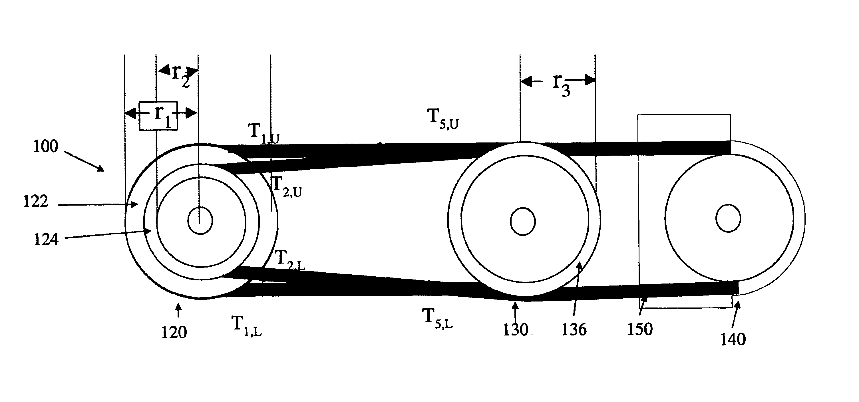
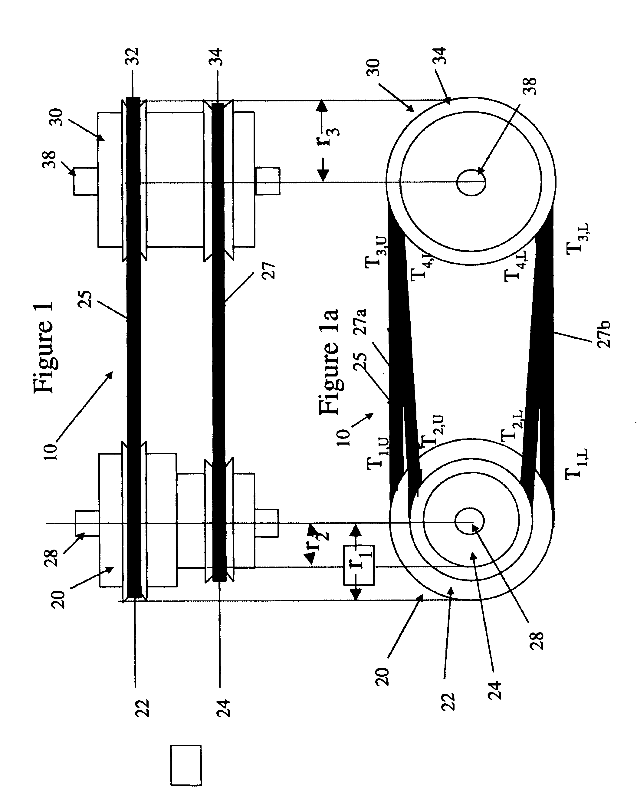
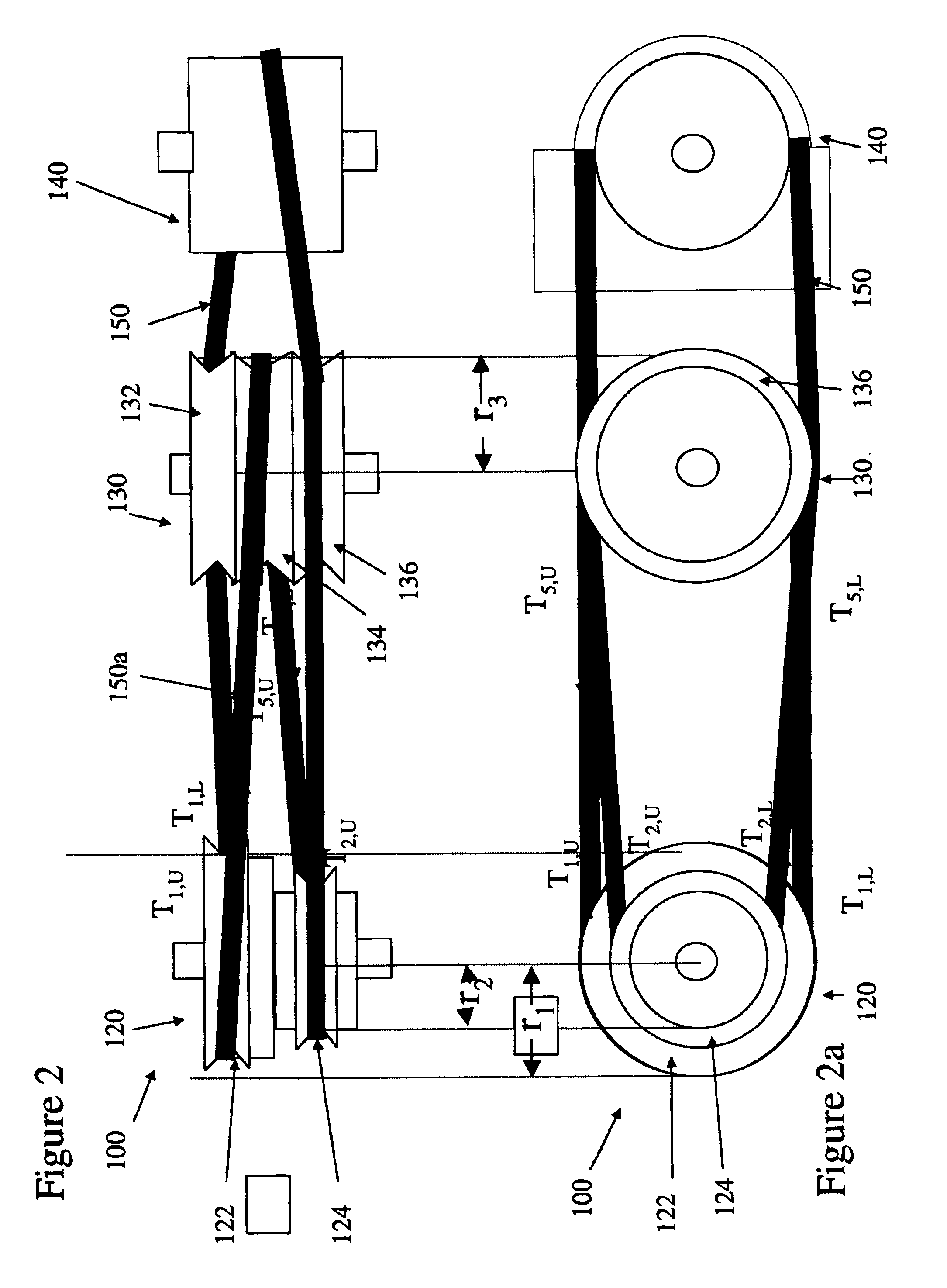
[0011]The present invention is a solid state thermal engine. A first embodiment is a rotary thermal actuator 10 and is illustrated in FIGS. 1 and 1a. FIG. 1 is an elevation view of the actuator 10, and FIG. 1a is a side view of the actuator 10.

[0012]The actuator 10 has drums 20 and 30 with axes 28 and 38 respectively. Attached to drum 20 are pulleys 22 and 24, and attached to drum 30 are pulleys 32 and 34. The radius (r2) of pulley 24 should be smaller than the radius (r1) of pulley 22. Pulleys 32 and 34 should have the same radius (r3). Pulleys 22 and 32 are connected to each other by a belt 25, and pulleys 24 and 34 are connected to each other by a belt 27. A ribbon, wire or coil spring could also be used in place of one or both of the belts 25 and 27. The belts 25 and 27 are under sufficient tension so that they do not slip over their respective pulleys. Pulleys 22 and 24 are locked together so that they turn with the same angular velocity, and pulleys 32 and 34 are locked togeth...


PUM


Abstract

A solid state thermal engine has two drums, each drum having two pulleys positioned thereon. Each pulley on the one drum is coupled to its counterpart pulley on the other drum via a belt, chain or other connector. One of the belts, referred to as the active belt, is heated which causes the active belt to expand. The expansion decreases the tension on the active belt, and further causes the active belt and the pulleys on which it is positioned to rotate. In a preferred embodiment, the active belt is manufactured out of a memory metal such as NITINOL. In another embodiment, a system of several drums and pulleys are used to implement a chain fall device.

Description

FIELD OF THE INVENTION[0001]The present invention relates to solid state thermal engines, and in particular, solid state thermal engines that use shape changing and shape memory alloys.BACKGROUND OF THE INVENTION[0002]Micro-miniature machines and robots are used in applications that require efficiency and compactness. These machines and robots are normally powered by electric and / or pneumatic motors. Unfortunately, these motors are bulky, complex, and require tight machine tolerances. To overcome the shortcomings of motors that power micro-miniature machines and robots, shape changing alloys such as NITINOL have been used as actuators in place of these motors and machines. While the art has experienced some success in the use of shape changing alloys in micro-miniature machines and robots, simpler and more reliable actuators and motors are needed.SUMMARY OF THE INVENTION[0003]The present invention is a solid state thermal engine having a belt and pulley system. In its simplest form,...

Claims


Application Information

Patent Timeline
Patent Type & Authority Patents(United States)
IPC IPC(8): F02G1/00F02G1/04F16H7/02
CPCF02G1/04F16H7/02
Inventor HOWARD, ROBERT J.
Owner LOCKHEED MARTIN CORP
Why Eureka
Try Eureka